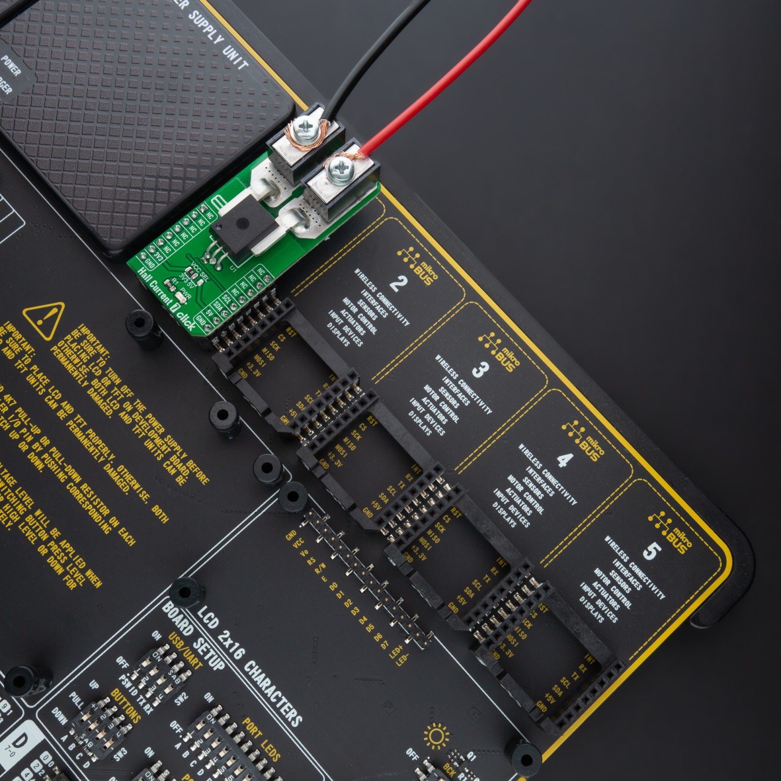
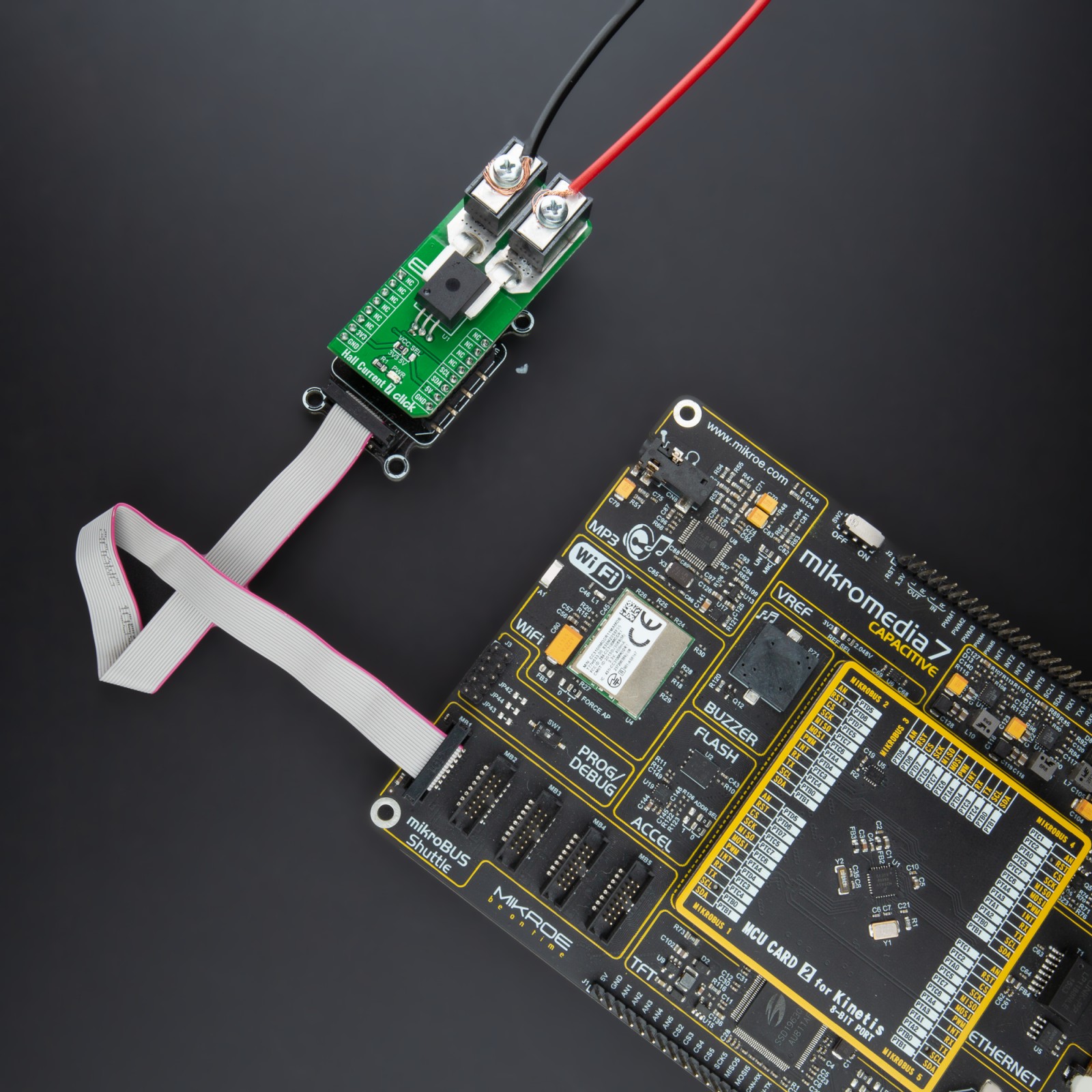
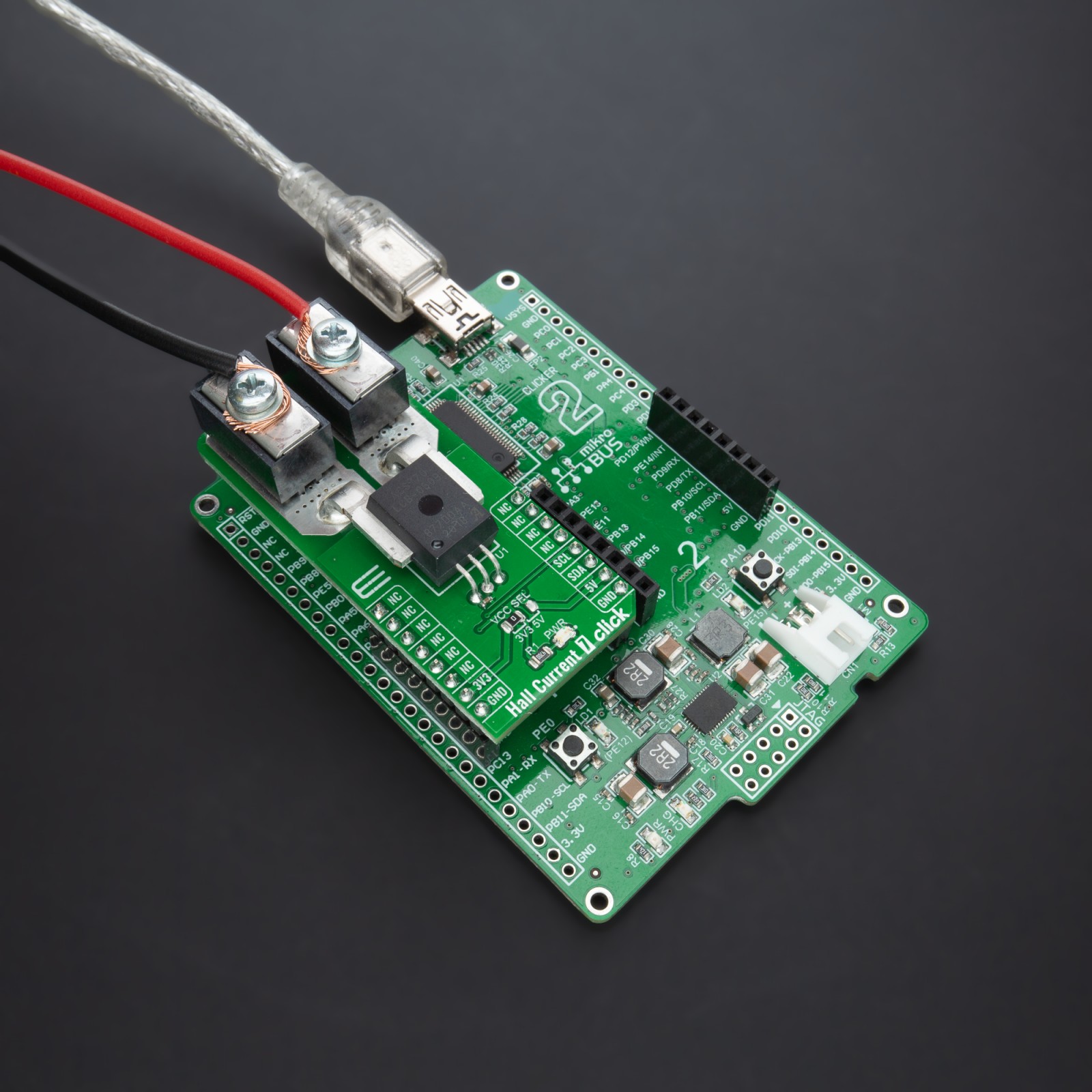
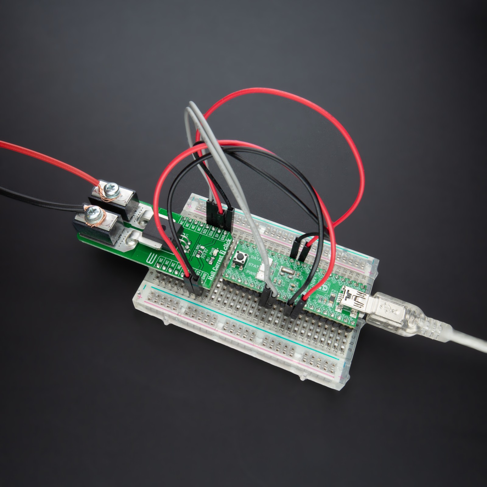
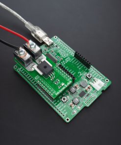
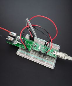
DO NOT TOUCH THE BOARD WHILE THE EXTERNAL POWER SUPPLY IS ON!
Note: This Click board™ needs to be used by trained personnel only while applying high voltages. Special care should be taken when working with hazardous voltage levels.
How does it work?
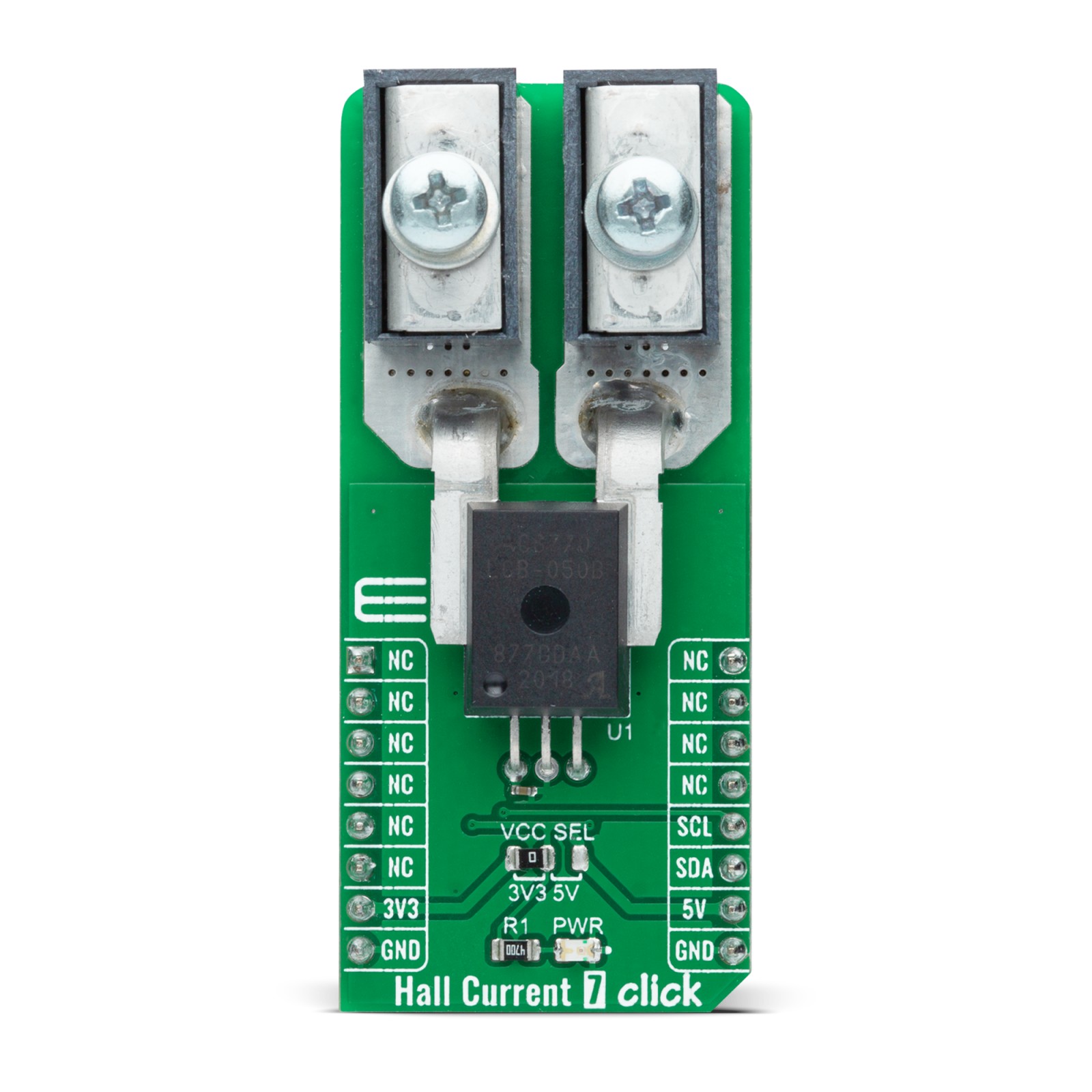
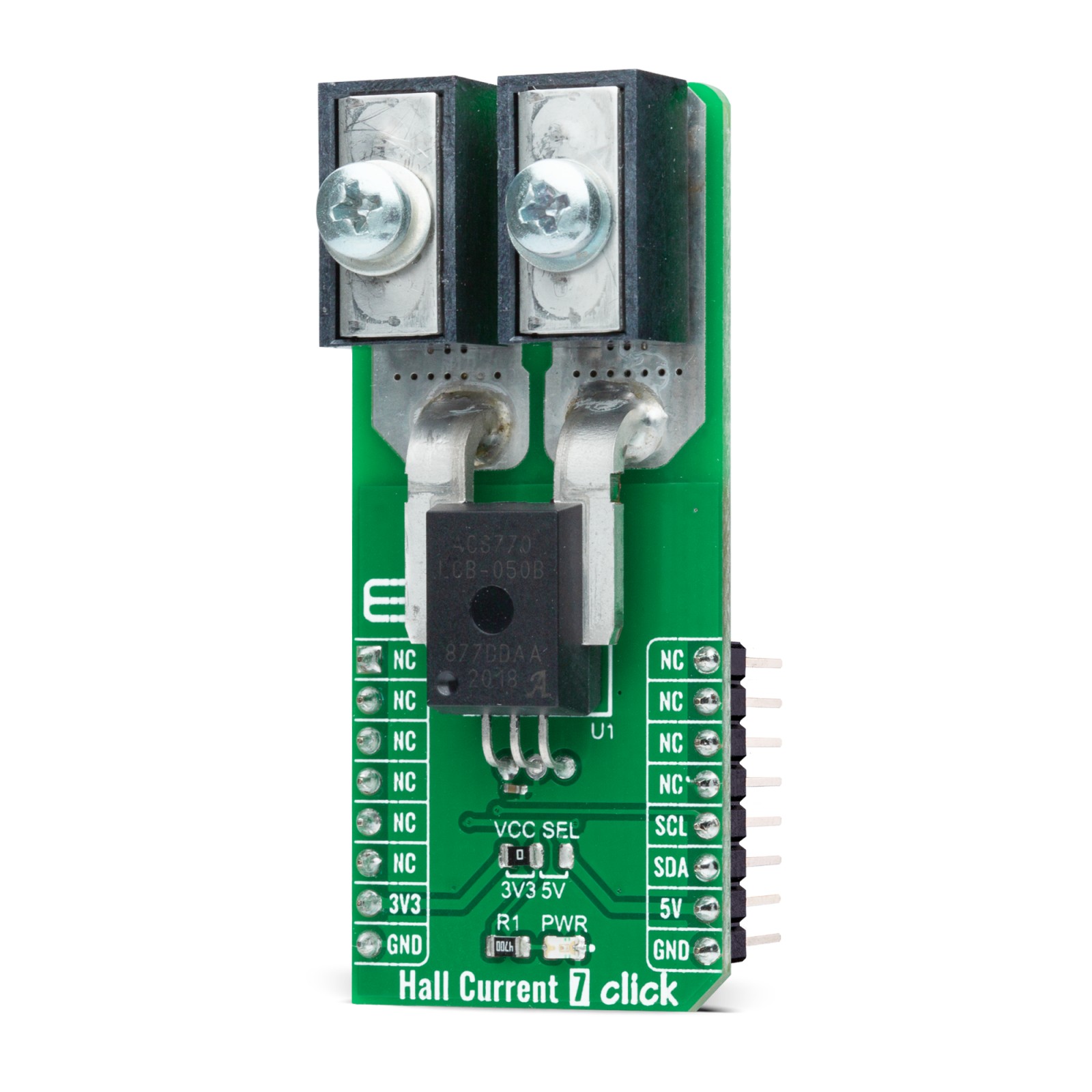
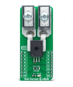
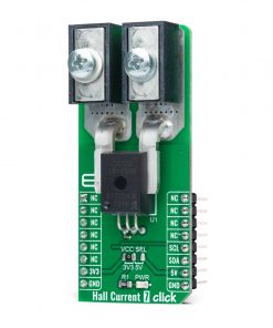
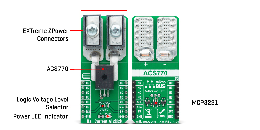
Hall Current 7 Click is based on the ACS770, a thermally enhanced, fully integrated, Hall effect-based high precision linear current sensor with 100µΩ current conductor from Allegro MicroSystems. This Hall-effect current sensor eliminates the need for a sense-resistor. The current flows directly into the integrated conductor, generating a magnetic field that will be measured. As current flows in its integrated conductor, an integrated low-hysteresis core concentrates the magnetic field that is then sensed by the Hall element with a typical accuracy of ±1% and 120 kHz bandwidth. This core also acts as a magnetic shield, rejecting external stray fields. The integrated conductor has 100μΩ resistance, providing ultralow-power loss.
The thickness of the copper conductor allows the survival of the device at high overcurrent conditions. The terminals of the conductive path are electrically isolated from the signal leads. This allows the ACS770 to be used in applications requiring electrical isolation without the use of optoisolators or other costly isolation techniques. The ACS770 outputs an analog signal that varies linearly with the bidirectional AC or DC primary sampled current. The analog signal is then brought to the analog to digital converter (ADC) that converts the output signal from the ACS770 into a digital value, which is available over the I2C interface.
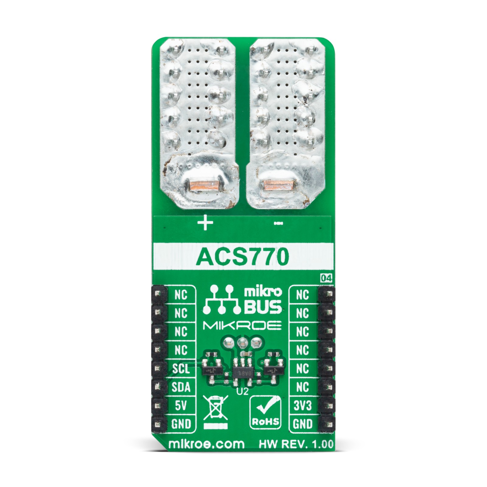
Hall Current 7 Click communicates with MCU through the MCP3221, a successive approximation A/D converter with a 12-bit resolution from Microchip, using a 2-wire I2C compatible interface. This device provides one single-ended input with very low-power consumption, a low maximum conversion current, and a Standby current of 250 μA and 1 μA, respectively. Data can be transferred at rates of up to 100 kbit/s in the Standard and up to 400 kbit/s in the Fast Mode. Also, maximum sample rates of 22.3 kSPS with the MCP3221 are possible in a Continuous-Conversion Mode with a clock rate of 400 kHz.
This Click board™ is designed to operate with both 3.3V and 5V logic voltage levels selected via the VCC SEL jumper. It allows for both 3.3V and 5V capable MCUs to use the I2C communication lines properly. However, the Click board™ comes equipped with a library that contains easy to use functions and an example code which can be used, as a reference, for further development.
Specifications
Type
Current sensor,Measurements
Applications
Can be used for applications like motor control, load detection and management, DC-to-DC converter control, and similar applications that require accurate and reliable current sensing.
On-board modules
Hall Current 7 Click is based on the ACS770, a thermally enhanced, fully integrated, Hall effect-based high precision linear current sensor with 100µΩ current conductor from Allegro MicroSystems.
Key Features
Ultralow-power loss, high precision, improved total output error, high reliability, high accuracy, extremely stable output offset voltage, and more.
Interface
I2C
Feature
No ClickID
Compatibility
mikroBUS™
Click board size
L (57.15 x 25.4 mm)
Input Voltage
3.3V or 5V
Pinout diagram
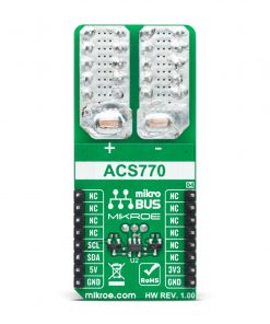
This table shows how the pinout on Hall Current 7 Click corresponds to the pinout on the mikroBUS™ socket (the latter shown in the two middle columns).
Onboard settings and indicators
Label | Name | Default | Description |
---|---|---|---|
LD1 | PWR | – | Power LED Indicator |
JP1 | VCC SEL | Left | Power Supply Voltage Selection 3V3/5V: Left position 3V3, Right position 5V |
Hall Current 7 Click electrical specifications
Description | Min | Typ | Max | Unit |
---|---|---|---|---|
Supply Voltage | -0.3 | – | 6 | V |
Working voltage for basic isolation | – | – | 700 | V(RMS) |
Primary Sampled Current | -100 | – | +100 | A |
Sensitivity | 19.52 | 20 | 20.48 | mV/A |
Accuracy | – | ±0.6 | – | % |
Operating Temperature Range | -40 | – | +150 | °C |
Software Support
We provide a library for the Hall Current 7 Click on our LibStock page, as well as a demo application (example), developed using MikroElektronika compilers. The demo can run on all the main MikroElektronika development boards.
Library Description
The library covers all the necessary functions that enables the usage of the Hall Current 7 Click board™. It offers reading raw data from output register and calculations for raw output voltage, current and average current passing through the on board Hall Effect Sensor.
Key functions:
uint16_t hallcurrent7_read_voltage ( uint16_t v_ref );
– Function is used to calculate raw output voltage.int16_t hallcurrent7_calc_current ( uint16_t v_ref );
– Function is used to calculate current.int16_t hallcurrent7_avg_current ( uint16_t v_ref );
– Function is used to calculate average current and correct for output error.
Examples description
The application is composed of three sections :
- System Initialization – Initializes I2C module and LOG structure.
- Application Initialization – Initalizes I2C driver and makes an initial log.
- Application Task – This example shows the capabilities of the Hall Current 7 Click board™ by measuring current passing through the on board Hall Effect Sensor and displaying data every two seconds. In order to get correct clculations user should change “v_ref” value to his own power supply voltage.
void application_task ( ) { current = hallcurrent7_avg_current( v_ref ); IntToStr( current, log_txt ); mikrobus_logWrite( "Current: ", _LOG_TEXT ); mikrobus_logWrite( log_txt, _LOG_TEXT ); mikrobus_logWrite( "mA", _LOG_LINE ); mikrobus_logWrite( "------------------------", _LOG_LINE ); Delay_ms( 2000 ); }
The full application code, and ready to use projects can be found on our LibStock page.
Other mikroE Libraries used in the example:
- I2C
- UART
- Conversions
Additional notes and informations
Depending on the development board you are using, you may need USB UART click, USB UART 2 click or RS232 click to connect to your PC, for development systems with no UART to USB interface available on the board. The terminal available in all MikroElektronika compilers, or any other terminal application of your choice, can be used to read the message.
mikroSDK
This Click board™ is supported with mikroSDK – MikroElektronika Software Development Kit. To ensure proper operation of mikroSDK compliant Click board™ demo applications, mikroSDK should be downloaded from the LibStock and installed for the compiler you are using.
For more information about mikroSDK, visit the official page.