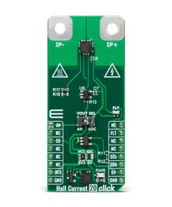
Hall Current 20 Click
R490.00 ex. VAT
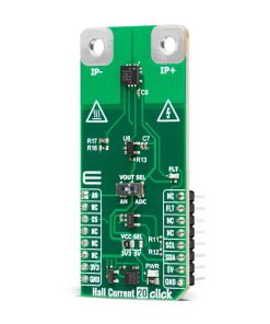
Hall Current 20 Click is a compact add-on board designed for precise high-current measurement with minimal power loss. This board features the ACS37220LEZATR-150B3, a low-resistance Hall-effect current sensor from Allegro Microsystems. Featuring an ultra-low internal resistance of less than 100μΩ, it supports a bidirectional sensing range of ±150A with 8.8mV/A sensitivity while ensuring high accuracy through factory calibration. The sensor’s differential Hall plates provide strong immunity to external magnetic fields, and its AEC-Q100 Grade 0 qualification ensures reliable operation in extreme temperatures. The output signal is also processed via an LMV321 OpAmp and can be converted to a digital value using the onboard MCP3221 ADC. With overcurrent fault detection for enhanced system protection, Hall Current 20 Click is ideal for applications such as automotive systems, industrial equipment, and power monitoring solutions requiring accurate and reliable current sensing.
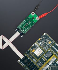
Hall Current 20 Click is fully compatible with the mikroBUS™ socket and can be used on any host system supporting the mikroBUS™ standard. It comes with the mikroSDK open-source libraries, offering unparalleled flexibility for evaluation and customization. What sets this Click board™ apart is the groundbreaking ClickID feature, enabling your host system to seamlessly and automatically detect and identify this add-on board.
Stock: Lead-time applicable.
| 5+ | R465.50 |
| 10+ | R441.00 |
| 15+ | R416.50 |
| 20+ | R400.82 |
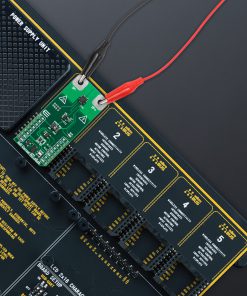
 DO NOT TOUCH THE BOARD WHILE THE LOAD IS CONNECTED!
Note: This Click board™ needs to be used by trained personnel only while applying high voltages. Special care should be taken when working with hazardous voltage levels.
How does it work?
Hall Current 20 Click is based on the ACS37220LEZATR-150B3, a low-resistance current sensor from Allegro Microsystems that delivers highly accurate current measurements with minimal power loss. This Click board™ incorporates the ACS37220 sensor, an integrated Hall-effect current sensor that enables precise monitoring of currents flowing through its primary conductor. With an exceptionally low internal resistance of less than 100μΩ, the ACS37220 minimizes power dissipation and enhances efficiency in applications requiring high-current sensing. It supports a wide bidirectional sensing range of ±150A and offers a sensitivity of 8.8mV/A, ensuring reliable and high-resolution current measurements in demanding environments.

The ACS37220 sensor uses two differential Hall plates to detect the magnetic field generated by the current flowing through its primary conductor. This differential sensing mechanism effectively suppresses common-mode interference and external magnetic field influences, enhancing measurement stability. Additionally, the device is factory-calibrated to maintain high accuracy across its entire operational range, ensuring consistent and precise performance over time. Its robust design meets the stringent automotive AEC-Q100 Grade 0 qualification, allowing it to operate reliably under extreme temperatures. It is well-suited for applications in automotive systems, industrial equipment, and power monitoring solutions.
The output analog signal from ACS37220 is forwarded to the input of the operational amplifier, the LMV321 low-voltage rail-to-rail OpAmp from Texas Instruments. The output of the LMV321 OpAmp has a stable unity gain, acting as a buffer so that the host MCU can sample the output voltage of the ACS37220 via the AN pin of the mikroBUS™ socket. The ACS37220’s analog output can also be converted to a digital value using MCP3221, a successive approximation A/D converter with a 12-bit resolution from Microchip, using a 2-wire I2C compatible interface, or sent, as mentioned, directly to an analog pin of the mikroBUS™ socket labeled as AN. Selection can be performed via an onboard SMD switch labeled VOUT SEL, placing it in an appropriate position marked as AN and ADC.
In addition to these pins, the board uses the FLT pin and a red FLT LED indicator to serve as an overcurrent fault output. This feature enables rapid short-circuit detection, enhancing system protection by providing immediate fault indication in case of excessive current flow.
This Click board™ can operate with either 3.3V or 5V logic voltage levels selected via the VCC SEL jumper. This way, both 3.3V and 5V capable MCUs can use the communication lines properly. Also, this Click board™ comes equipped with a library containing easy-to-use functions and an example code that can be used as a reference for further development.
Specifications
Type
Current sensor,Measurements
Applications
Ideal for applications such as automotive systems, industrial equipment, and power monitoring solutions
On-board modules
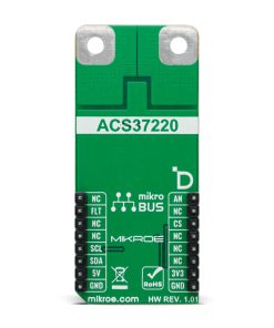
ACS37220LEZATR-150B3 – low-resistance current sensor from Allegro Microsystems
Key Features
Bidirectional current sensing range, ultra-low internal conductor resistance, high immunity to external magnetic fields, factory-calibrated for high accuracy, AEC-Q100 Grade 0 qualified, analog and digital output options, overcurrent fault detection, and more
Interface
Analog,I2C
Feature
ClickID
Compatibility
mikroBUS™
Click board size
L (57.15 x 25.4 mm)
Input Voltage
3.3V or 5V
Pinout diagram
This table shows how the pinout on Hall Current 20 Click corresponds to the pinout on the mikroBUS™ socket (the latter shown in the two middle columns).
| Notes | Pin | Pin | Notes | ||||
|---|---|---|---|---|---|---|---|
| Analog Output | AN | 1 | AN | PWM | 16 | NC | |
| NC | 2 | RST | INT | 15 | FLT | Overcurrent Fault | |
| ID COMM | CS | 3 | CS | RX | 14 | NC | |
| NC | 4 | SCK | TX | 13 | NC | ||
| NC | 5 | MISO | SCL | 12 | SCL | I2C Clock | |
| NC | 6 | MOSI | SDA | 11 | SDA | I2C Data | |
| Power Supply | 3.3V | 7 | 3.3V | 5V | 10 | 5V | Power Supply |
| Ground | GND | 8 | GND | GND | 9 | GND | Ground |
Onboard settings and indicators
| Label | Name | Default | Description |
|---|---|---|---|
| LD1 | PWR | – | Power LED Indicator |
| LD2 | FLT | – | Overcurrent Fault LED Indicator |
| JP1 | VCC SEL | Left | Power Voltage Level Selection 3V3/5V: Left position 3V3, Right position 5V |
| SW1 | VOUT SEL | Right | Output Voltage A/D Selection AN/ADC: Left position AN, Right position ADC |
Hall Current 20 Click electrical specifications
| Description | Min | Typ | Max | Unit |
|---|---|---|---|---|
| Supply Voltage | 3.3 | – | 5 | V |
| Current Sensing Range | -150 | – | +150 | A |
| Sensitivity | – | 8.8 | – | mV/A |
Software Support
Hall Current 20 Click demo application is developed using the NECTO Studio, ensuring compatibility with mikroSDK‘s open-source libraries and tools. Designed for plug-and-play implementation and testing, the demo is fully compatible with all development, starter, and mikromedia boards featuring a mikroBUS™ socket.
Example Description
This example demonstrates the use of Hall Current 20 Click board by reading and displaying the input current measurements.
Key Functions
hallcurrent20_cfg_setupConfig Object Initialization function.hallcurrent20_initInitialization function.hallcurrent20_calib_offsetThis function calibrates the zero current offset value.hallcurrent20_calib_resolutionThis function calibrates the data resolution at the known load current.hallcurrent20_read_currentThis function reads the input current level [A].
Application Init
Initializes the driver and calibrates the zero current offset and data resolution at 3A load current.
Application Task
Reads the input current measurements and displays the results on the USB UART approximately once per second.
Application Output
This Click board can be interfaced and monitored in two ways:
- Application Output – Use the “Application Output” window in Debug mode for real-time data monitoring. Set it up properly by following this tutorial.
- UART Terminal – Monitor data via the UART Terminal using a USB to UART converter. For detailed instructions, check out this tutorial.
Additional Notes and Information
The complete application code and a ready-to-use project are available through the NECTO Studio Package Manager for direct installation in the NECTO Studio. The application code can also be found on the MIKROE GitHub account.
Resources
Downloads
| Weight | 19 g |
|---|---|
| Brand | MikroElektronika |