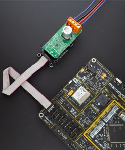
H-Bridge 6 Click
R795.00 ex. VAT
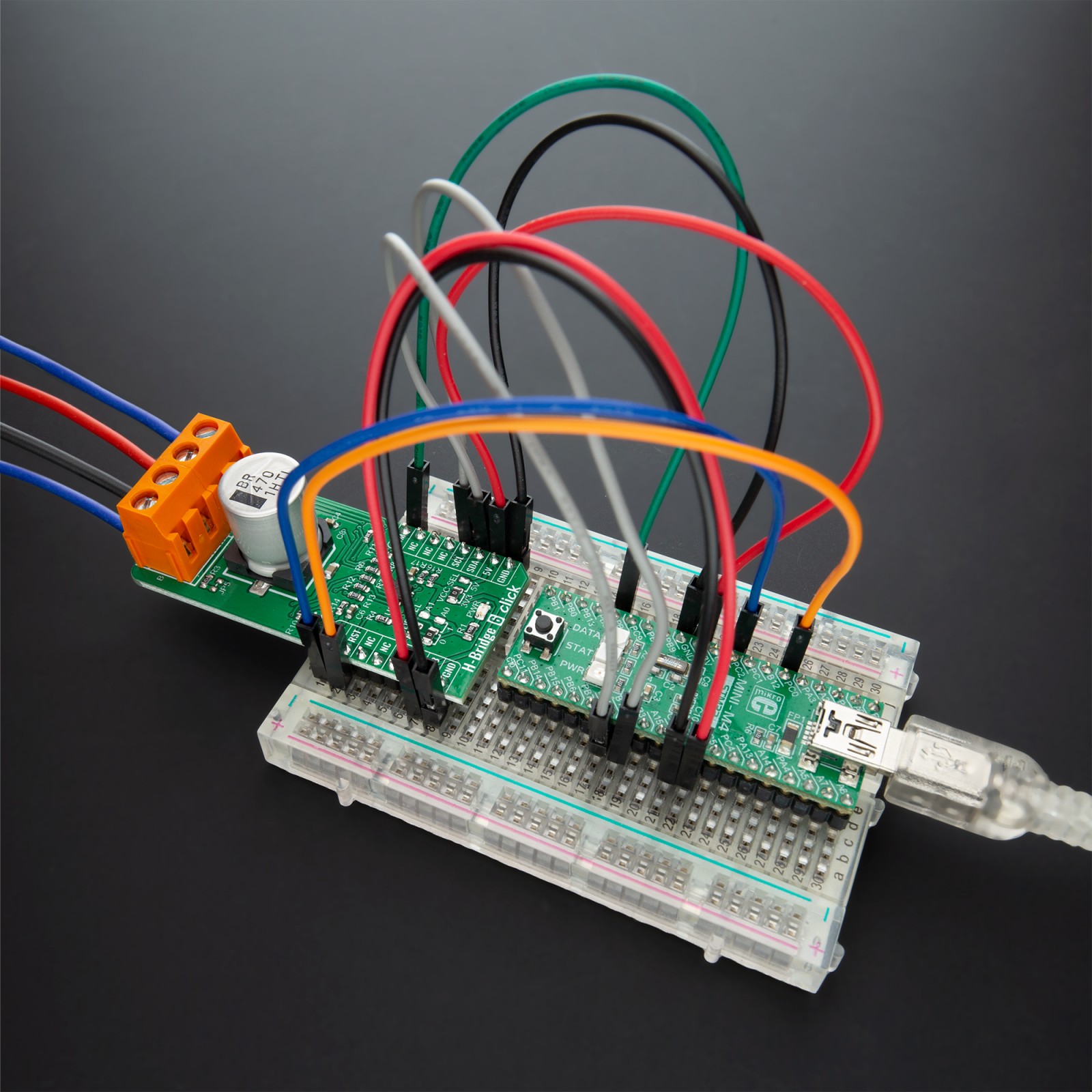
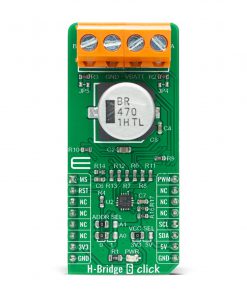
H-Bridge 6 Click is a compact add-on board that contains a DC motor driver for automotive applications. This board features the VNHD7008AY, an H-bridge motor driver for automotive DC motor driving from STMicroelectronics. The VNHD7008AY, features an undervoltage shutdown, load current limitation, overload active power limitation, overtemperature shutdown, and more. This Click board™ also contains the PCA9538A, a low-voltage 8-bit GPIO expander for communication between MCU and motor driver. H-Bridge 6 Click is suitable for automotive motor control applications like automotive brushed DC motor, or in applications such as body control module (BCM), car-seat control, and others.
H-Bridge 6 Click is supported by a mikroSDK compliant library, which includes functions that simplify software development. This Click board™ comes as a fully tested product, ready to be used on a system equipped with the mikroBUS™ socket.
Stock: Lead-time applicable.
| 5+ | R755.25 |
| 10+ | R715.50 |
| 15+ | R675.75 |
| 20+ | R650.31 |
How does it work?
H-Bridge 6 Click is based on the VNHD7008AY, a DC motor driver for automotive applications that integrates a full protected dual high-side driver and protection for the external power MOSFETs from STMicroelectronics. This Click board™ can interface the MCU to select the motor direction and the brake conditions via input signals on INA and INB pins, but also possesses a MultiSense pin for a motor-current monitor. Two selection pins (SEL0 and SEL1) are available to address to the MCU the information available on the MultiSense pin. It operates from a single power supply input labeled as VBATT in a range from 4V to 28V which can be directly connected to a DC voltage supply. Also, this device is fully protected against supply under-voltage, output overcurrent, and device overtemperature events.

NOTE: To Power-On the VNHD7008AY from Stand-By Mode, it is recommended to toggle INA or INB or SEL0 or SEL1 pins from 0 to 1 state to come out from Stand-By Mode. Also, toggle the PWM pin from 0 to 1 state with a delay of 20μs to avoids any overstress on the device in case of an existing short-to-battery situation.
H-Bridge 6 Click communicates with MCU through a well-known 8bit I/O expander the PCA9538A from NXP Semiconductor using the standard I2C 2-Wire interface with a maximum frequency of 400kHz. The VNHD7008AY also allows the choice of the least significant bit (LSB) of its I2C slave address by positioning SMD jumpers labeled as ADDR SEL to an appropriate position marked as 0 and 1. In addition to this feature, this Click board™ also contains additional functionalities routed to the PWM, AN, and RST pins on the mikroBUS™ socket. The PWM pin, up to 20 kHz, allows to control of the speed of the motor in all possible conditions, whiles the AN pin labeled as MS allows monitoring the motor current, provides a voltage proportional to the battery value, and the information on the temperature of the VNHD7008AY. The RST pin has retained its reset function by default.
This Click board™ is designed to be operated with both 3.3V and 5V logic voltage levels that can be selected via VCC SEL jumper. This allows for both 3.3V and 5V capable MCUs to use the I2C communication lines properly. However, the Click board™ comes equipped with a library that contains easy to use functions and an example code that can be used as a reference for further development.
Specifications
Type
Brushed
Applications
Can be used for automotive motor control applications like automotive brushed DC motor, or in applications such as body control module (BCM), car-seat control, and others.
On-board modules
H-Bridge 6 Click is based on the VNHD7008AY, a DC motor driver for automotive applications that integrates a full protected dual high-side driver and protection for the external power MOSFETs from STMicroelectronics.
Key Features
Fully protected HSD with MultiSense feedback, undervoltage shutdown, overvoltage clamp, load current limitation, overload active power limitation, overtemperature shutdown, cross current protection, and more.
Interface
I2C,PWM
Feature
No ClickID
Compatibility
mikroBUS™
Click board size
L (57.15 x 25.4 mm)
Input Voltage
3.3V or 5V
Pinout diagram
This table shows how the pinout on H-Bridge 6 Click corresponds to the pinout on the mikroBUS™ socket (the latter shown in the two middle columns).
Onboard settings and indicators
| Label | Name | Default | Description |
|---|---|---|---|
| LD1 | PWR | – | Power LED Indicator |
| JP1 | VCC SEL | Left | Power Supply Voltage Selection 3V3/5V: Left position 3V3, Right position 5V |
| JP2-JP3 | ADDR SEL | Left | Communication interface selection: Left position 0, Right position 1 |
| JP4-JP5 | – | Unpopulated | VBATT Short-Circuit Protection Selection |
H-Bridge 6 Click electrical specifications
| Description | Min | Typ | Max | Unit |
|---|---|---|---|---|
| Supply Voltage | 4 | – | 28 | V |
| Maximum Output Current | – | – | Internally Limited |
A |
| Operating Temperature Range | -40 | – | +150 | °C |
Software Support
We provide a library for the H-Bridge 6 Click on our LibStock page, as well as a demo application (example), developed using MikroElektronika compilers. The demo can run on all the main MikroElektronika development boards.
Library Description
The library covers all the necessary functions to control the H-Bridge 6 Click board™. A library performs communication with the device via the I2C interface. Using the PWM function, we can adjust the engine speed and direction.
Key functions:
void hbridge6_generic_write ( uint8_t reg, uint8_t tx_data )– Generic write function.uint8_t hbridge6_generic_read ( uint8_t reg )– Generic read function.void hbridge6_set_direction ( uint8_t direction )– Set the direction function.
Examples description
The application is composed of three sections :
- System Initialization – Initializes I2C and start to write log.
- Application Initialization – Initialization driver enables – I2C, reset the device and set default configuration, initialization and configure the PWM, also write log.
- Application Task – (code snippet) This is an example that demonstrates the use of H-Bridge 6 Click board™. It shows moving in the clockwise direction of rotation and moving in the counterclockwise direction of rotation from slow to fast speed. All data logs write on USB uart changes.
void application_task ( )
{
    mikrobus_logWrite( "-----------------------", _LOG_LINE );
    mikrobus_logWrite( "       Clockwise       ", _LOG_LINE );
    hbridge6_set_direction( HBRIDGE6_DIRECTION_CLOCKWISE );
    pwm_duty_cycle = 100;

    while ( pwm_duty_cycle < ( pwm_max_duty / 3 ) )
    {
        pwm_duty_cycle += 50;
        mikrobus_logWrite( " >", _LOG_TEXT );
        hbridge6_pwm_set_duty( pwm_duty_cycle );
        Delay_ms( 100 );
    }

    mikrobus_logWrite( "", _LOG_LINE );
    mikrobus_logWrite( "-----------------------", _LOG_LINE );
    mikrobus_logWrite( "         Brake         ", _LOG_LINE );
    hbridge6_set_direction( HBRIDGE6_DIRECTION_BRAKE );
    Delay_ms( 3000 );

    mikrobus_logWrite( "-----------------------", _LOG_LINE );
    mikrobus_logWrite( "    Counterclockwise   ", _LOG_LINE );
    hbridge6_set_direction( HBRIDGE6_DIRECTION_COUNTERCLOCKWISE );
    pwm_duty_cycle = 100;
    Delay_ms( 1000 );

    while ( pwm_duty_cycle < ( pwm_max_duty / 3 ) )
    {
        pwm_duty_cycle += 50;
        mikrobus_logWrite( " <", _LOG_TEXT );
        hbridge6_pwm_set_duty( pwm_duty_cycle );
        Delay_ms( 100 );
    }

    mikrobus_logWrite( "", _LOG_LINE );
    mikrobus_logWrite( "-----------------------", _LOG_LINE );
    mikrobus_logWrite( "         Brake         ", _LOG_LINE );
    hbridge6_set_direction( HBRIDGE6_DIRECTION_BRAKE );
    Delay_ms( 1000 );

    hbridge6_pwm_stop( );
    Delay_ms( 2000 );
    hbridge6_pwm_start( );
    Delay_ms( 1000 );
}
uint32_t hbridge6_pwm_init ( uint16_t freq )– Initializes the Timer module in PWM mode.void hbridge6_pwm_set_duty ( uint16_t duty )– The function changes PWM duty ratio.void hbridge6_pwm_start( )– Starts appropriate PWM module.void hbridge6_pwm_stop( )– Stops appropriate PWM module.
The full application code, and ready to use projects can be found on our LibStock page.
Other mikroE Libraries used in the example:
- I2C
- PWM
- UART
Additional notes and informations
Depending on the development board you are using, you may need USB UART click, USB UART 2 click or RS232 click to connect to your PC, for development systems with no UART to USB interface available on the board. The terminal available in all MikroElektronika compilers, or any other terminal application of your choice, can be used to read the message.
mikroSDK
This Click board™ is supported with mikroSDK – MikroElektronika Software Development Kit. To ensure proper operation of mikroSDK compliant Click board™ demo applications, mikroSDK should be downloaded from the LibStock and installed for the compiler you are using.
For more information about mikroSDK, visit the official page.
Resources
Downloads
| Weight | 28 g |
|---|---|
| Brand | MikroElektronika |


