H-Bridge 18 Click
R410.00 ex. VAT
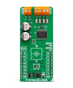
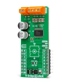
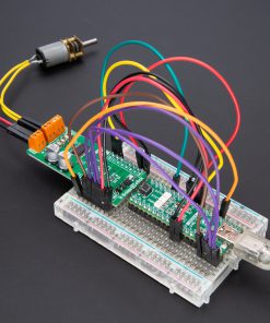
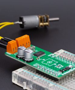
H-Bridge 18 Click is a compact add-on board that controls brushed DC (BDC) and stepper motors. This board features the DRV8904-Q1, an automotive-grade multi-channel half-bridge driver from Texas Instruments, offering advanced diagnostics and protection features. The DRV8904-Q1 supports independent, sequential, or parallel motor driving modes, with each half-bridge delivering up to 1A (6A maximum current for paralleled outputs). It features an SPI interface with daisy-chain capability, eight programmable PWM generators, and comprehensive fault detection, including short-circuit, undervoltage, and thermal overload protection. Additionally, it includes a low-power Sleep mode, a fault indication pin (FLT), and dedicated test points for monitoring the connected load. H-Bridge 18 Click is ideal for HVAC flap control, LED lighting, multiple brushed DC motor systems, and solenoid actuation, where precision control and system reliability are crucial.
H-Bridge 18 Click is fully compatible with the mikroBUS™ socket and can be used on any host system supporting the mikroBUS™ standard. It comes with the mikroSDK open-source libraries, offering unparalleled flexibility for evaluation and customization. What sets this Click board™ apart is the groundbreaking ClickID feature, enabling your host system to seamlessly and automatically detect and identify this add-on board.
Stock: Lead-time applicable.
| 5+ | R389.50 |
| 10+ | R369.00 |
| 15+ | R348.50 |
| 20+ | R335.38 |
How does it work?
H-Bridge 18 Click is based on the DRV8904-Q1, an automotive-grade multi-channel half-bridge driver from Texas Instruments, designed for precise control of brushed DC (BDC) motors and stepper motors, offering advanced diagnostics and protection features. The DRV8904-Q1 supports independent, sequential, or parallel motor driving modes, with each half-bridge rated for a continuous output current of 1A (6A maximum current for paralleled outputs). Its architecture allows full control of motor movement, including forward, reverse, coasting, and braking operations, ensuring performance in demanding environments. Thanks to its versatile capabilities, H-Bridge 18 Click is well-suited for various automotive, industrial, and consumer electronics applications, including HVAC flap control, LED lighting, multiple brushed DC motor systems, and solenoid actuation, where precision control and system protection are critical.

This Click board™ communicates with the host MCU through a standard 16-bit SPI interface. It operates at speeds of up to 5MHz and features daisy-chain support for integration into complex systems. One of its key features is the integration of eight programmable PWM generators, allowing for precise current limiting during motor operation or controlled LED dimming. The DRV8904-Q1 also incorporates an array of diagnostic and protection mechanisms to enhance reliability.
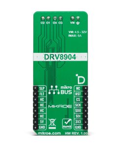
These include real-time fault monitoring and reporting, ensuring immediate detection and response to issues such as short circuits, undervoltage, or thermal overload. Additionally, the device features a low-current open-load detection (OLD) mode, which enables accurate identification of open-load conditions even when the nominal load current is minimal, alongside a passive OLD mode for offline fault detection. The H-Bridge 18 Click operates from an external power supply connected to the VM terminal, with a recommended operating range of 4.5V to 32V.
In addition to the SPI interface, H-Bridge 18 Click includes dedicated control pins for enhanced power management and fault monitoring. The SLP pin allows the device to enter a low-power Sleep mode when set to a LOW logic level while setting it to HIGH enables the driver to operate normally. Additionally, the FLT pin serves as a fault indication signal, alerting the system when an error condition is detected. To provide clear visual feedback, the board integrates corresponding LED indicators: a yellow SLEEP LED to signal when the device is in low-power mode and a red FAULT LED to indicate the presence of a detected fault, ensuring real-time status monitoring and improved system reliability. Besides the load connection terminals, the board includes four dedicated hooks that serve as test points for the attached load, allowing for convenient monitoring and diagnostics during operation.
This Click board™ can operate with either 3.3V or 5V logic voltage levels selected via the VCC SEL jumper. This way, both 3.3V and 5V capable MCUs can use the communication lines properly. Also, this Click board™ comes equipped with a library containing easy-to-use functions and an example code that can be used as a reference for further development.
Specifications
Type
Brushed
Applications
Ideal for HVAC flap control, LED lighting, multiple brushed DC motor systems, and solenoid actuation
On-board modules
DRV8904-Q1 – automotive multi-channel half-bridge driver with advanced diagnostics from Texas Instruments
Key Features
Multi-channel half-bridge driver, supports independent, sequential, and parallel motor driving modes, each half-bridge delivers up to 1A continuous current, SPI interface, eight programmable PWM generators for motor control, fault detection, low-current and passive Open-Load Detection (OLD) modes, and more
Interface
SPI
Feature
ClickID
Compatibility
mikroBUS™
Click board size
L (57.15 x 25.4 mm)
Input Voltage
3.3V or 5V,External
Pinout diagram
This table shows how the pinout on H-Bridge 18 Click corresponds to the pinout on the mikroBUS™ socket (the latter shown in the two middle columns).
| Notes | Pin | Pin | Notes | ||||
|---|---|---|---|---|---|---|---|
| NC | 1 | AN | PWM | 16 | SLP | Sleep Mode Control | |
| ID SEL | RST | 2 | RST | INT | 15 | FLT | Fault Indicator |
| SPI Select / ID COMM | CS | 3 | CS | RX | 14 | NC | |
| SPI Clock | SCK | 4 | SCK | TX | 13 | NC | |
| SPI Data OUT | SDO | 5 | MISO | SCL | 12 | NC | |
| SPI Data IN | SDI | 6 | MOSI | SDA | 11 | NC | |
| Power Supply | 3.3V | 7 | 3.3V | 5V | 10 | 5V | Power Supply |
| Ground | GND | 8 | GND | GND | 9 | GND | Ground |
Onboard settings and indicators
| Label | Name | Default | Description |
|---|---|---|---|
| LD1 | PWR | – | Power LED Indicator |
| LD2 | SLEEP | – | Sleep Mode LED Indicator |
| LD3 | FAULT | – | Fault LED Indicator |
| JP1 | VCC SEL | Left | Power Voltage Level Selection 3V3/5V: Left position 3V3, Right position 5V |
H-Bridge 18 Click electrical specifications
| Description | Min | Typ | Max | Unit |
|---|---|---|---|---|
| Supply Voltage | 3.3 | – | 5 | V |
| External Power Supply | 4.5 | – | 32 | V |
| Output Current | – | – | 6 | A |
Software Support
H-Bridge 18 Click demo application is developed using the NECTO Studio, ensuring compatibility with mikroSDK‘s open-source libraries and tools. Designed for plug-and-play implementation and testing, the demo is fully compatible with all development, starter, and mikromedia boards featuring a mikroBUS™ socket.
Example Description
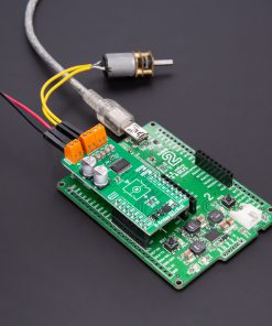
This example demonstrates the operation of the H-Bridge 18 Click board, which provides control over two DC motors using an H-Bridge driver. The application initializes the board and alternates between different motor states, including forward, reverse, coast, and braking, to demonstrate bidirectional motor control.
Key Functions
hbridge18_cfg_setupThis function initializes Click configuration structure to initial values.hbridge18_initThis function initializes all necessary pins and peripherals used for this Click board.hbridge18_default_cfgClick Default Configuration function.hbridge18_enable_deviceThis function enables the H-Bridge 18 device by setting the sleep pin high.hbridge18_disable_deviceThis function disables the H-Bridge 18 device by setting the sleep pin low.hbridge18_set_motor_stateThis function sets the motor state for the selected motor (coast, forward, reverse, brake low-side, or brake high-side).
Application Init
Initializes the logger and the H-Bridge 18 Click board. Configures the motor driver to the default settings, preparing it for operation.
Application Task
Alternates motor states in a sequence to demonstrate different control functionalities. The motors are set to move forward and reverse, followed by coasting and braking, repeating the cycle continuously.
Application Output
This Click board can be interfaced and monitored in two ways:
- Application Output – Use the “Application Output” window in Debug mode for real-time data monitoring. Set it up properly by following this tutorial.
- UART Terminal – Monitor data via the UART Terminal using a USB to UART converter. For detailed instructions, check out this tutorial.
Additional Notes and Information
The complete application code and a ready-to-use project are available through the NECTO Studio Package Manager for direct installation in the NECTO Studio. The application code can also be found on the MIKROE GitHub account.
Resources
Downloads
| Weight | 21 g |
|---|---|
| Brand | MikroElektronika |