H-Bridge 17 Click
R335.00 ex. VAT
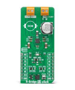
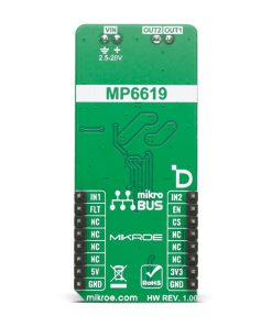
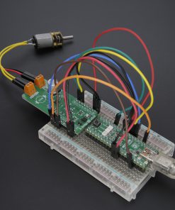
H-Bridge 17 Click is a compact add-on board for driving brushed DC motors, solenoids, and actuators. This board features the MP6619L, an H-bridge motor driver IC from MPS, capable of delivering high motor currents while operating from a wide supply voltage range of 2.5V to 28V. This Click board™ features flexible control via mikroBUS™ pins, configurable current limits (1A, 2A, or 4A) through the ISET SEL jumper, and robust safety mechanisms, including fault detection and overcurrent protection. H-Bridge 17 Click is ideal for applications in industrial automation, automotive systems, and consumer electronics that require efficient and safe motor control.
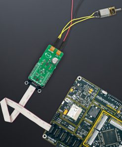
H-Bridge 17 Click is fully compatible with the mikroBUS™ socket and can be used on any host system supporting the mikroBUS™ standard. It comes with the mikroSDK open-source libraries, offering unparalleled flexibility for evaluation and customization. What sets this Click board™ apart is the groundbreaking ClickID feature, enabling your host system to seamlessly and automatically detect and identify this add-on board.
Stock: Lead-time applicable.
| 5+ | R318.25 |
| 10+ | R301.50 |
| 15+ | R284.75 |
| 20+ | R274.03 |
How does it work?
H-Bridge 17 Click is based on the MP6619L, an H-bridge motor driver IC from MPS designed for driving brushed DC motors, solenoids, and actuators. The MP6619L operates from an external supply voltage ranging between 2.5V and 28V via the VIN terminal and delivers high motor currents, ensuring reliable performance even under demanding conditions. This Click board™ is ideal for applications requiring precise motor control and robust safety mechanisms, offering reliable performance in industrial, automotive, and consumer settings.

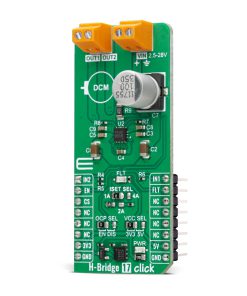
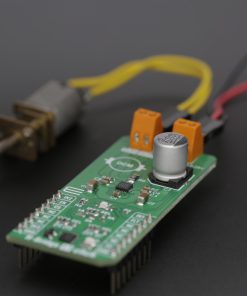
This Click board™ provides flexible control through several pins on the mikroBUS™ socket. The IN1 and IN2 pins control the output channels (OUT1 and OUT2), while the EN pin turns the motor driver IC ON or OFF. For added customization, the MP6619L features a configurable current limit that can be set using the ISET SEL jumper. This jumper allows users to select between three current limit values: 1A, 2A, or 4A. For 1A and 2A, the jumper is placed in the corresponding position, while for 4A, the jumper position must be left open, requiring the removal of a specific resistor.
H-Bridge 17 Click also incorporates several safety and diagnostic features. The FLT pin acts as a fault indicator, and it works in combination with a red FLT LED to signal if any protection circuits, such as overcurrent, overtemperature, overvoltage, or undervoltage lockout, are activated. This ensures that users are immediately informed of fault conditions, enabling quick troubleshooting. Additionally, the overcurrent protection (OCP) can be turned ON or OFF using the OCP SEL jumper, providing further flexibility in configuring the board to suit specific application requirements.
This Click board™ can operate with either 3.3V or 5V logic voltage levels selected via the VCC SEL jumper. This way, both 3.3V and 5V capable MCUs can use the communication lines properly. Also, this Click board™ comes equipped with a library containing easy-to-use functions and an example code that can be used as a reference for further development.
Specifications
Type
Brushed
Applications
Ideal for applications in industrial automation, automotive systems, and consumer electronics
On-board modules
MP6619L – H-bridge motor driver from MPS
Key Features
Up to 4A motor current, wide input voltage range, controllable via several pins, current limit configuration, several safety features alongside overcurrent protection, and more
Interface
GPIO
Feature
ClickID
Compatibility
mikroBUS™
Click board size
L (57.15 x 25.4 mm)
Input Voltage
3.3V or 5V,External
Pinout diagram
This table shows how the pinout on H-Bridge 17 Click corresponds to the pinout on the mikroBUS™ socket (the latter shown in the two middle columns).
| Notes | Pin | Pin | Notes | ||||
|---|---|---|---|---|---|---|---|
| OUT2 Channel Control | IN2 | 1 | AN | PWM | 16 | IN1 | OUT1 Channel Control |
| Chip Enable | EN | 2 | RST | INT | 15 | FLT | Fault Interrupt |
| ID COMM | CS | 3 | CS | RX | 14 | NC | |
| NC | 4 | SCK | TX | 13 | NC | ||
| NC | 5 | MISO | SCL | 12 | NC | ||
| NC | 6 | MOSI | SDA | 11 | NC | ||
| Power Supply | 3.3V | 7 | 3.3V | 5V | 10 | 5V | Power Supply |
| Ground | GND | 8 | GND | GND | 9 | GND | Ground |
Onboard settings and indicators
| Label | Name | Default | Description |
|---|---|---|---|
| LD1 | PWR | – | Power LED Indicator |
| LD2 | FLT | – | Fault LED Indicator |
| JP1 | VCC SEL | Left | Power Voltage Level Selection 3V3/5V: Left position 3V3, Right position 5V |
| JP2 | OCP SEL | Left | Overcurrent Protection Selection EN/DIS: Left position EN, Right position DIS |
H-Bridge 17 Click electrical specifications
| Description | Min | Typ | Max | Unit |
|---|---|---|---|---|
| Supply Voltage | 3.3 | – | 5 | V |
| External Power Supply | 2.5 | – | 28 | V |
| Output Current | 1 | – | 4 | A |
Software Support
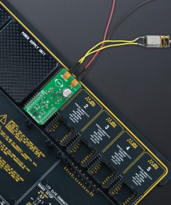
H-Bridge 17 Click demo application is developed using the NECTO Studio, ensuring compatibility with mikroSDK‘s open-source libraries and tools. Designed for plug-and-play implementation and testing, the demo is fully compatible with all development, starter, and mikromedia boards featuring a mikroBUS™ socket.
Example Description
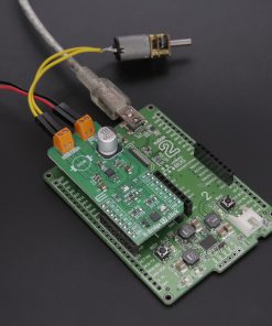
This example demonstrates the use of the H-Bridge 17 Click board by driving the motor in both directions with braking and freewheeling.
Key Functions
hbridge17_cfg_setupConfig Object Initialization function.hbridge17_initInitialization function.hbridge17_set_out_stateThis function is used to set the output state of the H-Bridge 17 Click board.hbridge17_ic_enableThis function enables driver IC by setting the EN (RST) pin on the high level of the H-Bridge 17 Click board.hbridge17_fault_indicationThis function reads the state of the FLT (INT) pin of the H-Bridge 17 Click board.
Application Init
Initializes the driver and enable H-Bridge driver IC.
Application Task
The demo application drives the motor in both directions with coasting and braking in between, every state lasts 5 seconds.
Application Output
This Click board can be interfaced and monitored in two ways:
- Application Output – Use the “Application Output” window in Debug mode for real-time data monitoring. Set it up properly by following this tutorial.
- UART Terminal – Monitor data via the UART Terminal using a USB to UART converter. For detailed instructions, check out this tutorial.
Additional Notes and Information
The complete application code and a ready-to-use project are available through the NECTO Studio Package Manager for direct installation in the NECTO Studio. The application code can also be found on the MIKROE GitHub account.
Resources
Downloads
| Weight | 21 g |
|---|---|
| Brand | MikroElektronika |