GSM-GPS Click
R1,250.00 ex. VAT
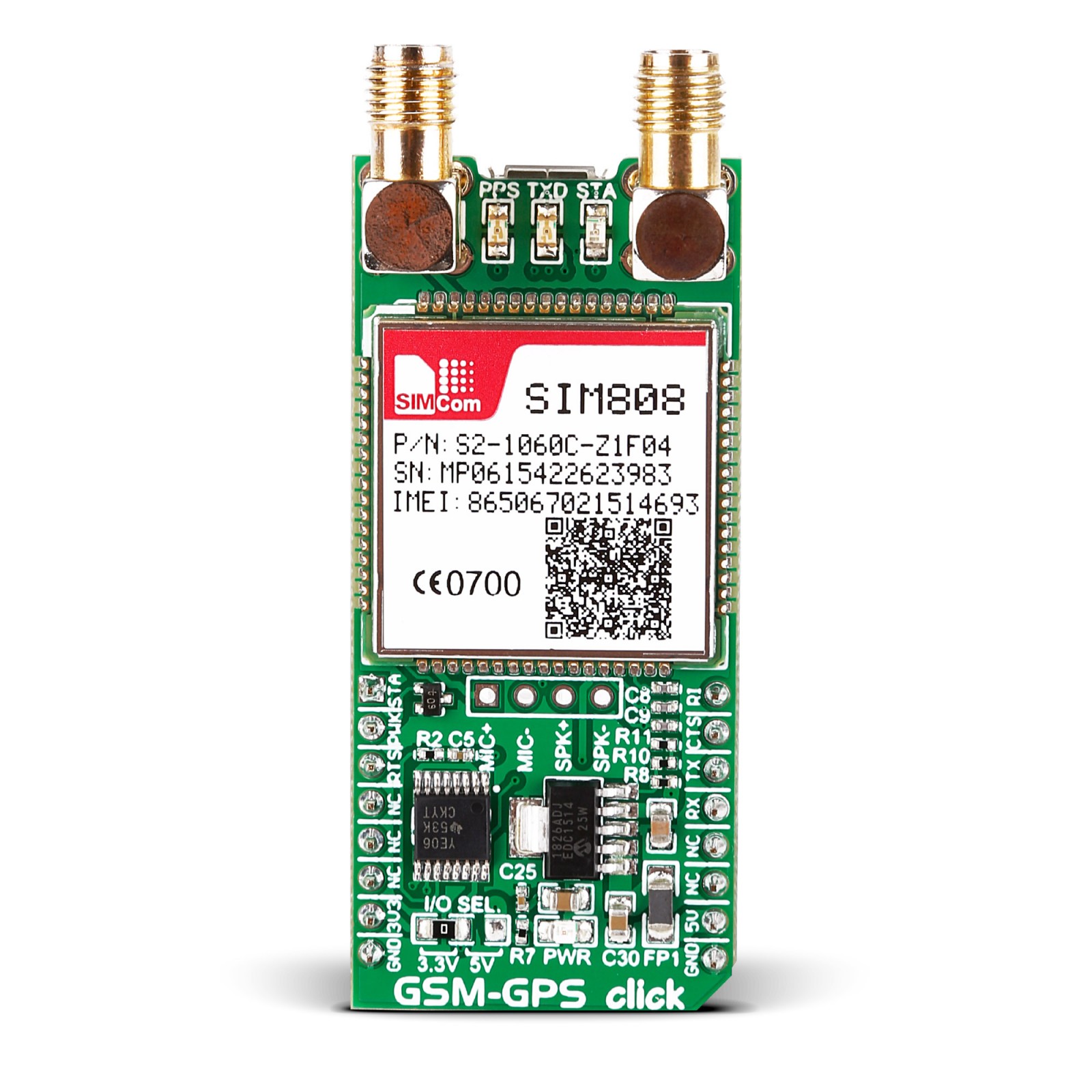
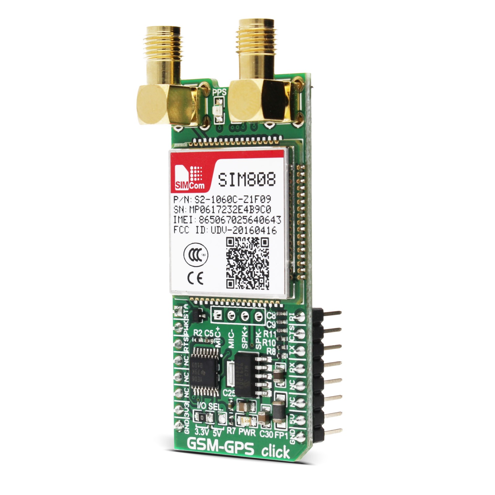
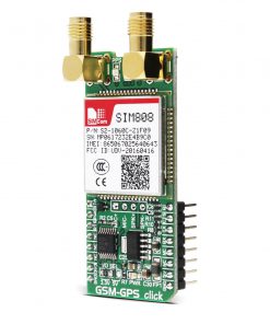
GSM-GPS Click is a compact add-on board that combines a GSM/GPRS and a GPS into a single device. This board features the SIM808, a GSM/GPRS+GPS module from SIMCom. The SIM808 GSM/GPRS engine is a quad-band module that works on frequencies GSM 850MHz, EGSM 900MHz, DCS 1800MHz, and PCS 1900MHz. It features a GPRS multi-slot class 12 (class 10 optional) and CS 1, 2, 3, and 4 coding schemes. The GPS engine offers one of the best-in-class acquisition and tracking sensitivity, Time-to-First-Fix (TTFF), and accuracy. This Click board™ makes the perfect solution for the development of applications based on M2M, smartphones, PDAs, trackers, and other mobile devices.
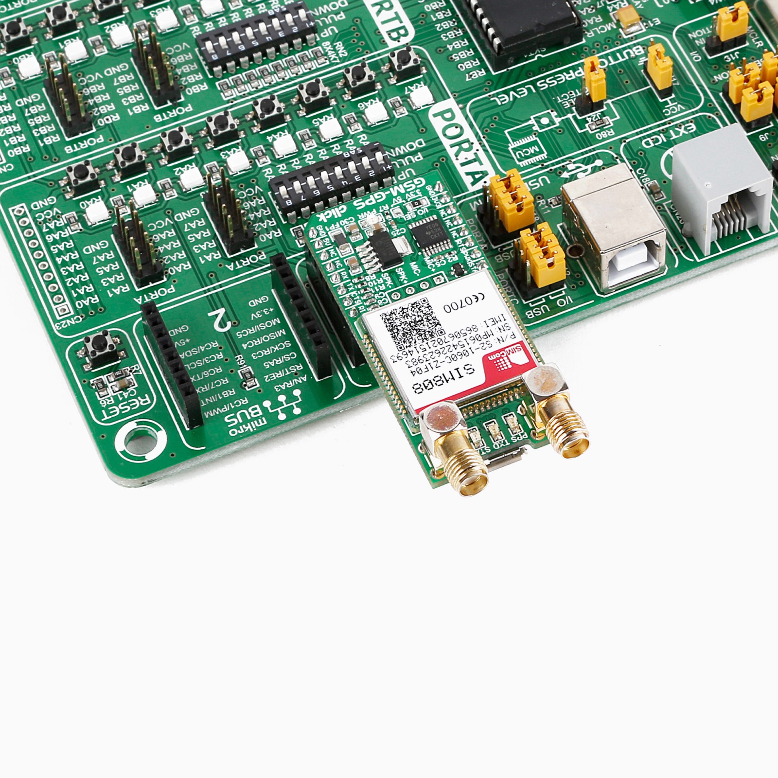
GSM-GPS Click is supported by a mikroSDK compliant library, which includes functions that simplify software development. This Click board™ comes as a fully tested product, ready to be used on a system equipped with the mikroBUS™ socket.
Stock: Lead-time applicable.
| 5+ | R1,187.50 |
| 10+ | R1,125.00 |
| 15+ | R1,062.50 |
| 20+ | R1,022.50 |
How does it work?
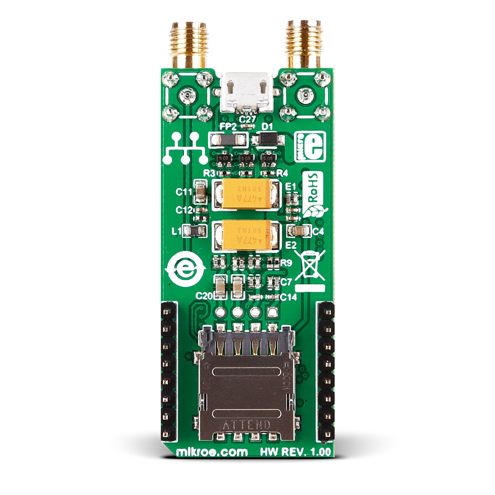
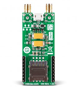
GSM-GPS Click is based on the SIM808, a GSM/GPRS+GPS module from SIMCom. The SIM808 is a highly integrated module and supports 0710 MUX protocol, TCP/UDP protocol, FTP/HTTP, MMS, POP3/SMTP, DTMF, jamming detection, audio record, SSL, optional Bluetooth 3.0, TTS CN, and has embedded AT. For connection with the outside world, this Click board™ features two SMA connectors for both GSM/GPRS and GPS radios, for which appropriate antennas MIKROE has in its offer for improved range and received signal strength. In addition, there is a micro-SIM slot beneath the GSM-GPS Click board and a micro-USB connector for interfacing it with a PC.
The SIM808 has three operational modes. The Normal mode has several functions, GSM/GPRS Sleep, GSM Idle, GSM Talk, GPRS Standby, GPRS Data, and Charge. Those functions the SIM808 module uses to transfer the data, connect between two subscribers, register to the GSM network, and more. The Power Down mode shuts down the baseband part of the module, the software is not active, and the serial port is not accessible, while the RTC remains active. In Minimum Functionality mode, the RF part of the module will not work, the SIM card will not be accessible, or both, but the serial port will still be accessible. The AT commands set the last two operational modes.
The GPRS class, 12 of the SIM808 can achieve up to 85.6Kbps data rates (downlink/uplink) while using a CS-4 coding scheme. It can handle SMS via GSM/GPRS by point-to-point MO and MT, SMS cell broadcast, text, and PDU mode. There is also support for PBCCH, PP-stack, and USSD.
The GPS receiver has 22 tracking and 66 acquisition channels, with a tracking sensitivity of -165dBm. The Cold Start is less sensitive with a -148dBm. The important part is TTFF which in Hot Start is less than a second but comes in some 32s for Cold Start. The accuracy is under 2.5m CEP in a horizontal position.
There are several LEDs for visual status presentation. The PPS stands for Pulse Per Second and is related to the receiver time. The TXD LED presents the network status, and the STA LED presents the power-on status. The GSM-GPS features a 4-pin header, the interface for differential audio output, and input for connecting the speaker and the microphone.
For communication with the host MCU, the SIM808 uses the UART interface with commonly used UART RX and TX pins as its default communication protocol, supporting baud rates from 1200bps up to 11520bps. The UART interface also comes with the RTS (request to send) and CTS (clear to send) pins. In addition, the Click board™ features other functions accessible through mikroBUS™ signals, such as Power-on status on the STA pin (the same status as on the STA LED). The power-down of the SIM808 can be achieved by pulling LOW for 1 second the PWK pin (power key). There is a ring indicator (RI) for apparent purposes. For logic level translation, this Click board™ uses the TXB0106, a 6-bit bidirectional level-shifting and voltage translator with auto-direction sensing and ESD protection from Texas Instruments.
This Click board™ can operate with either 3.3V or 5V logic voltage levels selected via the I/O SEL jumper. This way, both 3.3V and 5V capable MCUs can use the communication lines properly. However, the Click board™ comes equipped with a library containing easy-to-use functions and an example code that can be used, as a reference, for further development.
Specifications
Type
2G GPRS,GSM+GPS
Applications
GSM and GPS, remote functionality.
On-board modules
SIM808, SIM card slot, antenna connectors, Micro USB slot
Key Features
quad-band GSM: 850, EGSM 900, DCS 1800, PCS 1900, GPS TTF: 1s cold start; 28s warm start; 30s cold start, GPS Sensitivity: -148 dBm cold start; -159 re-acquisition; -165 dBm tracking
Interface
UART,USB
Feature
No ClickID
Compatibility
mikroBUS™
Click board size
L (57.15 x 25.4 mm)
Input Voltage
3.3V or 5V
Pinout diagram
This table shows how the pinout on GSM-GPS Click corresponds to the pinout on the mikroBUS™ socket (the latter shown in the two middle columns).
Onboard settings and indicators
| Label | Name | Default | Description |
|---|---|---|---|
| LD1B | TXD | – | Network Status LED Indicator |
| LD2C | STA | – | Power On Status LED Indicator |
| LD3B | PPS | – | Pulse Per Second Status LED Indicator |
| LD4A | PWR | – | Power LED Indicator |
| JP1 | I/O SEL | Left | Logic Level Voltage Selection 3V3/5V: Left position 3V3, Right position 5V |
GSM-GPS Click electrical specifications
| Description | Min | Typ | Max | Unit |
|---|---|---|---|---|
| Supply Voltage | 3.3 | – | 5 | V |
| GSM Range | 900 | – | 1900 | MHz |
| GPRS Data Rate | – | – | 85.6 | kbps |
| GPS TTF | <1 | – | 30 | S |
| GPS Tracking Sensitivity | – | -165 | – | dBm |
| GPS Accuracy | – | <2.5 | – | m |
Software Support
We provide a library for the GSM-GPS Click as well as a demo application (example), developed using MIKROE compilers. The demo can run on all the main MIKROE development boards.
Package can be downloaded/installed directly from NECTO Studio Package Manager(recommended), downloaded from our LibStock™ or found on MIKROE github account.
Library Description
This library contains API for GSM-GPS Click driver.
Key functions
-
Send command function with parameter.
-
GSM-GPS send SMS in PDU mode.
-
Generic parser function.
Example Description
This example reads and processes data from GSM-GPS click.
 void application_task ( void )
 {
     if ( app_connection_status == WAIT_FOR_CONNECTION )
     {
         // CGATT - request IMSI
         gsmgps_send_cmd_check( &gsmgps, GSMGPS_CMD_CGATT );
         app_error_flag = gsmgps_rsp_check(  );
         gsmgps_error_check( app_error_flag );
         Delay_ms( 500 );

         // CREG - network registration status
         gsmgps_send_cmd_check( &gsmgps, GSMGPS_CMD_CREG );
         app_error_flag = gsmgps_rsp_check(  );
         gsmgps_error_check( app_error_flag );
         Delay_ms( 500 );

         // CSQ - signal quality
         gsmgps_send_cmd( &gsmgps, GSMGPS_CMD_CSQ );
         app_error_flag = gsmgps_rsp_check(  );
         gsmgps_error_check( app_error_flag );
         Delay_ms( 5000 );
     }
     else
     {
         log_info( &logger, "CONNECTED TO NETWORK" );

         // SMS message format - PDU mode
         gsmgps_send_cmd_with_parameter( &gsmgps, GSMGPS_CMD_CMGF, "0" );
         app_error_flag = gsmgps_rsp_check(  );
         gsmgps_error_check( app_error_flag );
         Delay_ms( 3000 );

         for( ; ; )
         {
             // Get GPS info
             gps_parser_flag = 1;
             gsmgps_send_cmd_with_parameter( &gsmgps, GSMGPS_CMD_CGPSINF, "2" );
             app_error_flag = gsmgps_rsp_check(  );
             gsmgps_error_check( app_error_flag );
             Delay_ms( 3000 );

             if ( gps_parser_flag == 0 )
             {
                 log_printf( &logger, "> Sending message to phone number...rn" );
                 gsmgps_send_sms_pdu ( &gsmgps, SIM_SMSC, PHONE_NUMBER_TO_MESSAGE, gps_info_message );
                 app_error_flag = gsmgps_rsp_check(  );
                 gsmgps_error_check( app_error_flag );
                 Delay_ms( 10000 );
                 Delay_ms( 10000 );
                 Delay_ms( 10000 );
             }
         }
     }
 }
The full application code, and ready to use projects can be installed directly from NECTO Studio Package Manager(recommended), downloaded from our LibStock™ or found on Mikroe github account.
Other MIKROE Libraries used in the example:
- MikroSDK.Board
- MikroSDK.Log
- Click.Gsmgps
Additional notes and informations
Depending on the development board you are using, you may need USB UART click, USB UART 2 Click or RS232 Click to connect to your PC, for development systems with no UART to USB interface available on the board. UART terminal is available in all MIKROE compilers.
mikroSDK
This Click board™ is supported with mikroSDK – MIKROE Software Development Kit. To ensure proper operation of mikroSDK compliant Click board™ demo applications, mikroSDK should be downloaded from the LibStock and installed for the compiler you are using.
For more information about mikroSDK, visit the official page.
Resources
Downloads
| Weight | 31 g |
|---|---|
| Brand | MikroElektronika |

