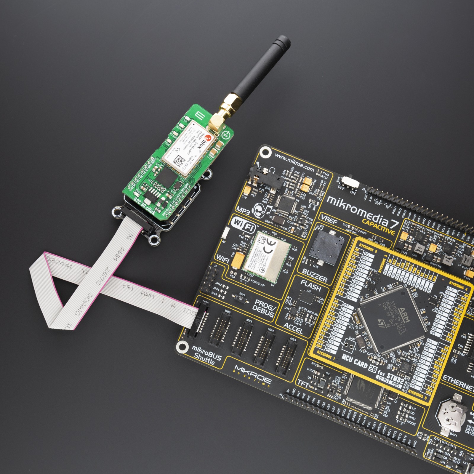
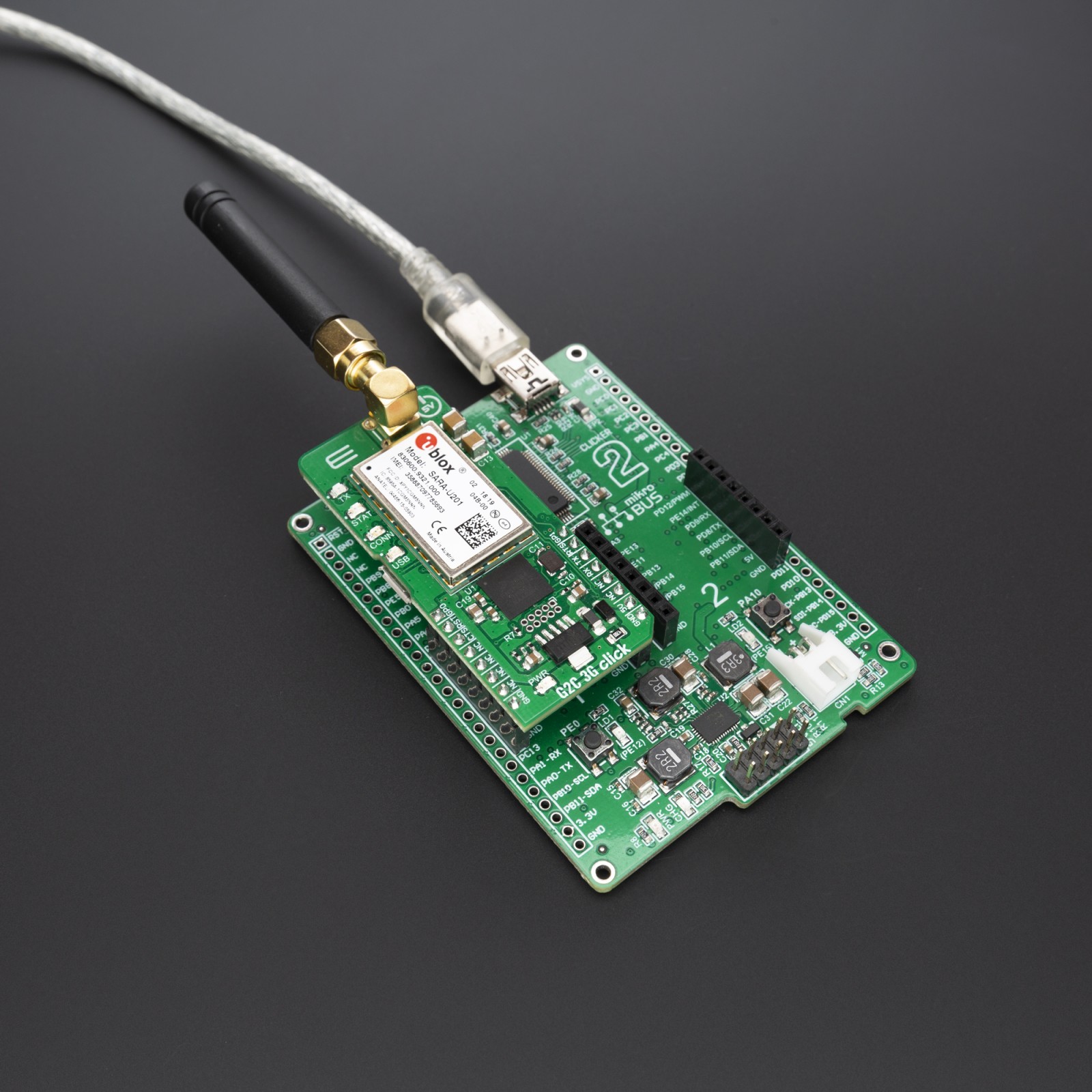
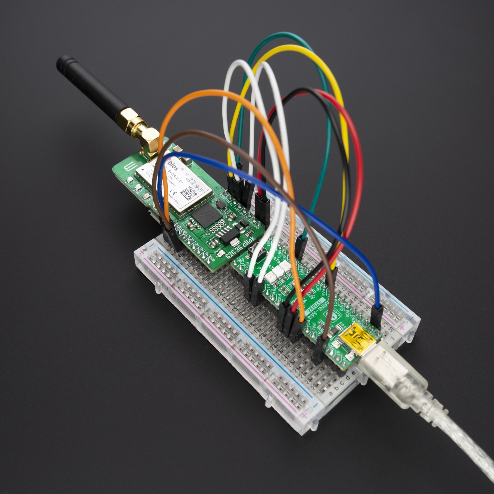
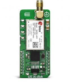
Go to Cloud (G2C) 3G Click
R1,650.00 ex. VAT
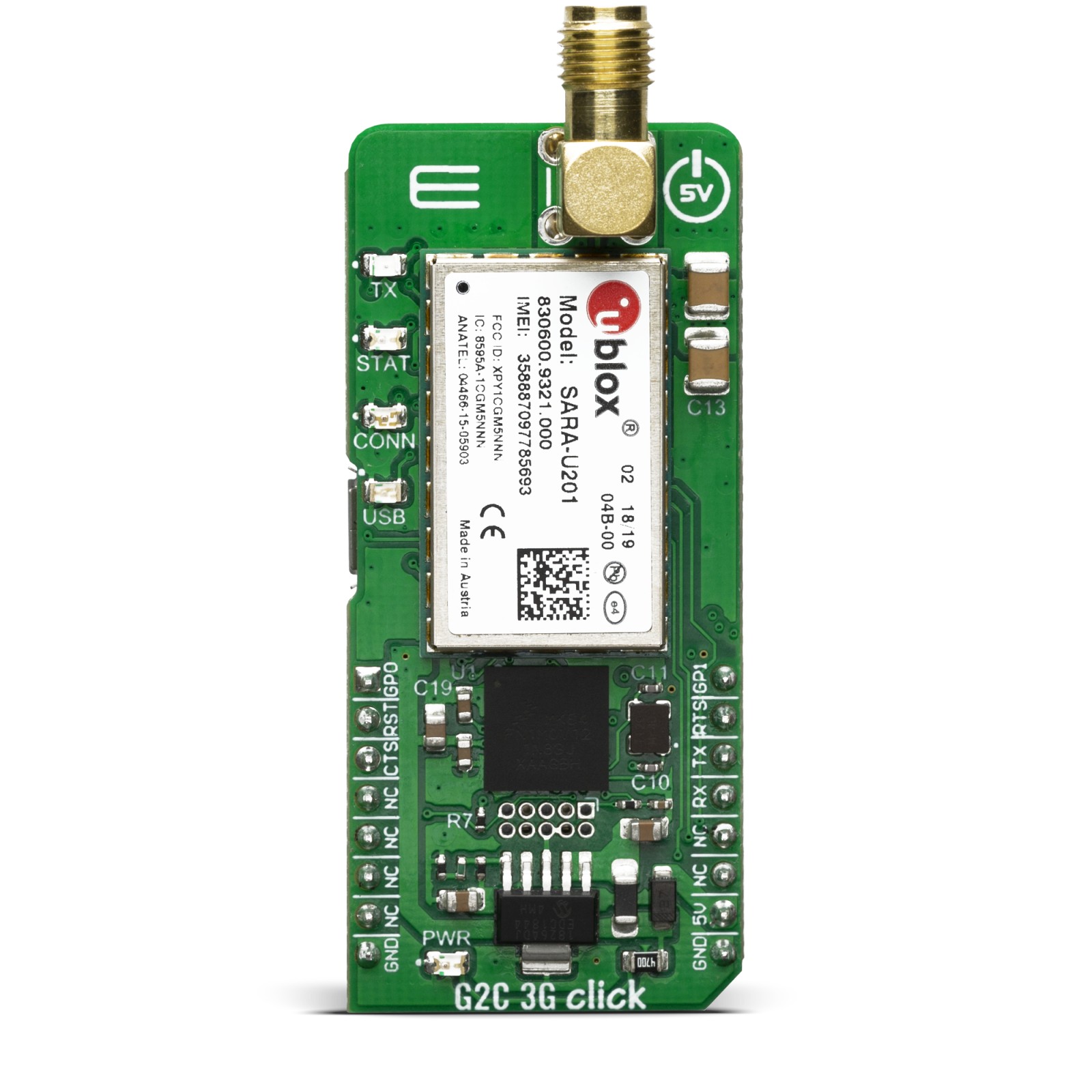
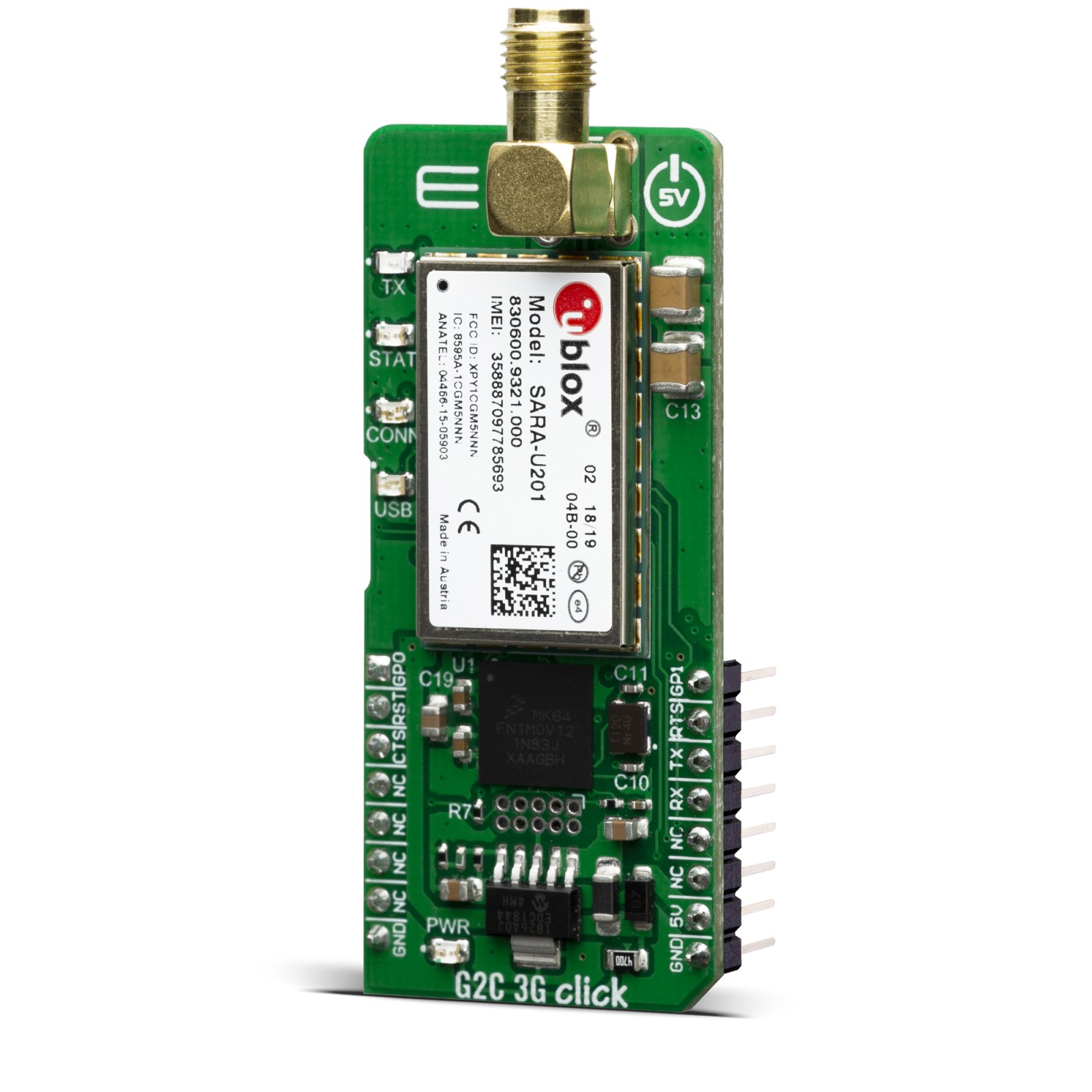
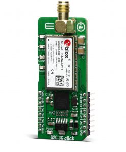
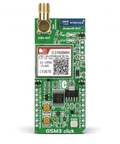
Go to Cloud (G2C) 3G click is a gateway Click board™ which provides a simple and reliable connection to the Click Cloud platform, a cloud-based rapid prototyping environment, hosted by Mikroe. G2C 3G offers an unprecedented simplicity for adding Click Cloud connectivity over UMTS/HSPA to any embedded application, by utilizing the simple UART interface: it can be configured and managed using a minimal set of well-documented AT commands. With the simplicity in mind, G2C 3G click represents an ideal solution for accessing user-friendly and intuitive Click Cloud, a simple yet powerful rapid prototyping cloud solution.
Learn all about the Click Cloud solution by visiting the official web page. All the necessary documentation to get you started, including the G2C 3G click User Manual, the AT Command Manual, and the Click Cloud Guide can be found in the documentation below, in the download section.
Stock: Lead-time applicable.
| 5+ | R1,567.50 |
| 10+ | R1,485.00 |
| 15+ | R1,402.50 |
| 20+ | R1,349.70 |
How does it work?
G2C 3G click is a Click board™ which allows connection to the feature-rich Click Cloud platform, over the 3.75G UMTS/HSPA network. G2C 3G click is envisioned so that users can easily add cloud connectivity and develop their own cloud-based applications, using only a set of simple AT commands, without having to delve into the complexity of web, hardware, and communications related development. Thanks to this simplified approach, everyone can benefit using the Click Cloud solution with G2C 3G click, since this Click board™ has all the necessary protocol and communication settings already implemented within its firmware. This saves a lot of time that would be otherwise wasted on the firmware development, and to adapting it to work with some third-party solution. Not to mention that such an effort would also require embedded and web programming proficiency, along with several other engineering skills. G2C 3G click, on the other hand, works in unity with Click Cloud solution, right out of the box.

G2C 3G click performs several tasks on its side, which are required to connect to the Click Cloud platform. To establish the connection, an access to a local UMTS/HSPA network with sim card option. For a reliable 3G (UMTS/HSPA) network connection, the Click board™ utilizes the u-Blox SARA U-201 module can be used worldwide.
The Click board™ uses a powerful MCU to manage the connection parameters, initialize the SARA U-201 module, and establish the connection with the Click Cloud platform. This allows to set up the connection in just a few simple steps, issuing a set of short AT commands, such as the SSID, password, device_ID, and so on. The complete documentation with in-depth explanation of each AT command and its response can be found in the AT Command Manual.
Besides the AT commands that are used to set up basic connection parameters, there are also AT commands that allow storing of the connection parameters, including the connection password, network SSID, device_ID, and other relevant connection data. These parameters can be stored in the non-volatile memory of the Go to Cloud (G2C) 3G click. It is possible to restore them by a single macro command, resulting in a very simplified connection procedure.
The functionality of the G2C 3G click will be constantly improved in the future. Therefore, G2C 3G click supports an upgrade of its firmware over the onboard USB connector. The firmware update process is very simple, using the familiar “HID Bootloader” software tool from MikroElektronika.
Go to Cloud (G2C) click is equipped with five LED indicators. They are used to indicate the presence of a power supply, the UMTS/HSPA connection, the USB connection, the data transmit flow and the connection with the Click Cloud solution. These LEDs provide visual feedback about the status of the G2C 3G click. This Click board™ requires only 5V power rail for proper operation.
Click cloud solution
Click Cloud solution is very simple to use, and it relies on a very comprehensive and intuitive web-based Graphical User Interface (WEB GUI). It allows the rapid development of cloud-based applications, offering a set of well-documented functionalities, specially tailored to offer the best experience when used with the Click board™ line of products. However, It can be used with other MikroElektronika products, as well.
Click Cloud hosted by MikroElektronika provides a clean, intuitive, and logical concept, abstracting the Click board™ as a “device” with its “device manifest” that contains a set of pre-configured or custom-created sensors, actuators, and other devices, typically found on various Click boards™. This concept allows very simplified management with nice and clean data representation. An interactive online help within the WEB GUI offers a detailed explanation of each feature of the Click Cloud solution. Besides using the WEB GUI, there is also the possibility to access the Click Cloud over mobile apps, based on IOS and Android OS platforms.
You can discover more about the features offered by Click Cloud solution, at the official Click Cloud page and by reading Go To Cloud click Quick Start User Guide.
Specifications
Type
3G UMTS,Cloud Routers,GSM/LTE
Applications
G2C 3G click is an IoT gateway Click board™ that allows simple and reliable connection and communication with the Click Cloud service, hosted by Mikroe. In combination with other Click board™ you may create your own IoT applications (smart appliances, process automation, data logging, and many others)
On-board modules
SARA U-201, a 3.75G UMTS/HSPA cellular network module from u-blox; MK64FN1M0VDC12 Arm® Cortex® M4 MCU from NXP
Key Features
All-in-one solution which provides an effortless IoT solution, using a simplified set of well-documented AT commands. Powerful 32bit MCU, coupled with the reliable and proven SARA U-201, a 3.75G UMTS/HSPA cellular network module, ensures smooth and effortless network connection to the Click Cloud
Interface
GPIO,UART,USB
Feature
No ClickID
Compatibility
mikroBUS™
Click board size
L (57.15 x 25.4 mm)
Input Voltage
5V
Pinout diagram
This table shows how the pinout on the G2C 3G click corresponds to the pinout on the mikroBUS™ socket (the latter shown in the two middle columns).
Onboard settings and indicators
| Label | Name | Default | Description |
|---|---|---|---|
| LD1 | PWR | – | Power LED Indicator |
| LD2 | TX | – | Data transmit indicator |
| LD3 | USB | – | USB service connection indicator |
| LD4 | STAT | – | Status and network indicator |
| LD5 | CONN | – | Broker service connection indicator |
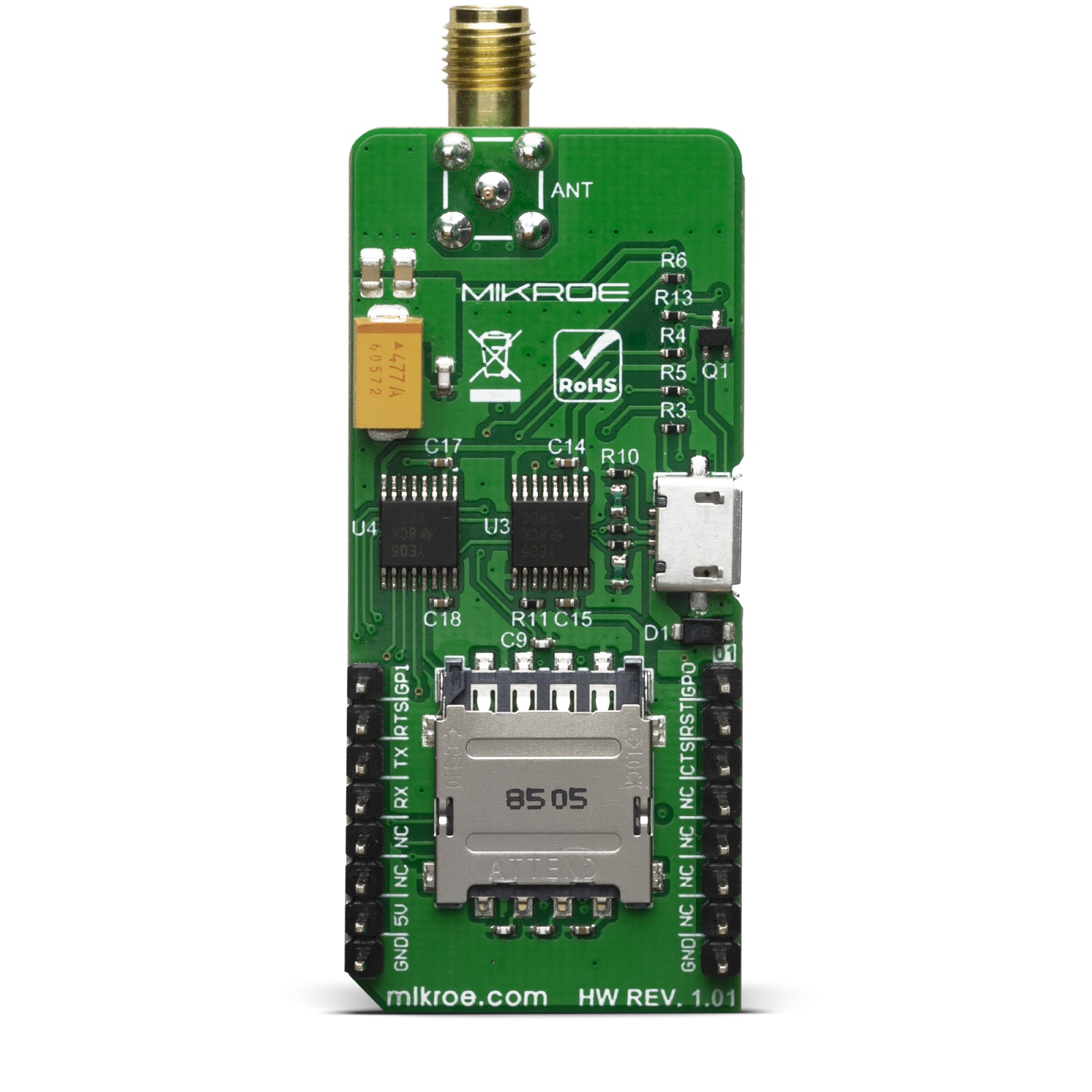
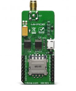
| CN1 | ANT | – | SMA antenna connector |
| CN2 | – | – | microUSB connector |
Software support
We provide a library for the Go to Cloud (G2C) 3G click on our LibStock page, as well as a demo application (example), developed using MikroElektronika compilers. The demo can run on all the main MikroElektronika development boards.
Library Description
The library carries generic command parser adopted for AT command based modules. The library contains an example for basic initialization of the actuator and sensor demo example.
Key functions:
void g2c3g_send_cmd ( char *p_cmd )– Simple AT Commandg2c3g_error_t g2c3g_actuator_sw_parser ( char *rsp, char *act_ref, g2c3g_actuator_sw_t *sw_state )– Actuator switch parserg2c3g_error_t g2c3g_actuator_cnt_parser ( char *rsp, char *act_ref, g2c3g_actuator_cnt_t *num_data )– Actuator counter parserg2c3g_error_t g2c3g_actuator_str_parser ( char *rsp, char *act_ref, g2c3g_actuator_str_t *str_data )– Actuator string parservoid g2c3g_send_broker_cfg ( char *brc_key, char *brc_password )– Parameter broker (device) settingvoid g2c3g_send_data_ref ( char *reference_buf, char *data_buf )– Parameter data setting
Examples description
The application is composed of the three sections :
- System Initialization – Initializes all necessary GPIO pins, UART used for communcation with G2C 3G module and UART used for logging.
- Application Initialization – Initializes driver and timer at 10ms. Initializes default handler (with 1500ms watchdog) with core init function. Module wake-up procedure is started and then the module is reset. This procedure must be performed at start of the program in order for the module to be ready for operation. Following commands are required in order to connect the module to click cloud.
- Application Task – Starts the process of reading responses and sending the data to the click cloud.
void application_init ( )
{
    // TIMER INIT
    g2c3g_timer_int_cfg( );

    // DRIVER INIT
    g2c3g_uart_driver_init( ( g2c3g_obj_t )&_MIKROBUS1_GPIO, ( g2c3g_obj_t )&_MIKROBUS1_UART );
    g2c3g_core_init( g2c3g_default_handler, 1500 );

    // MODULE POWER ON
    g2c3g_module_power( G2C3G_MODULE_POWER_ON );
    g2c3g_reset_module( );
    Delay_ms( 2000 );

    while( g2c3g_device_status( ) != G2C3G_STATUS_DEVICE_READY );
    Delay_ms( 2000 );

    mikrobus_logWrite( "****************************** START ** ", _LOG_LINE );

    g2c3g_send_cmd( &G2C3G_AT[ 0 ] );
    g2c3g_command_delay( );

    g2c3g_send_cmd( &G2C3G_AT_GMR[ 0 ] );
    g2c3g_command_delay( );

    g2c3g_send_cmd( &G2C3G_AT_CEN[ 0 ] );
    g2c3g_command_delay( );

    g2c3g_send_operator_cfg( &operator_apn[ 0 ],
                             &operator_username[ 0 ],
                             &operator_password[ 0 ] );
    g2c3g_command_delay( );

    g2c3g_send_cmd( &G2C3G_AT_NWC[ 0 ] );
    g2c3g_command_delay( );

    while( g2c3g_network_status( ) != 1 );
    Delay_ms( 2000 );

    g2c3g_send_broker_cfg( &device_key[ 0 ], &device_password[ 0 ] );
    g2c3g_command_delay( );

    g2c3g_send_cmd( &G2C3G_AT_BRC[ 0 ] );
    g2c3g_command_delay( );

    while( g2c3g_broker_status( ) != 1 );
    Delay_ms( 2000 );

    task_time = 0;
    mikrobus_logWrite( "********* CONNECT TO CLICK CLOUD ** ", _LOG_LINE );
}
void application_task ( )
{
    g2c3g_process( );

    if ( task_time > 2000 )
    {
        g2c3g_send_data_ref( &sensor_ref[ 0 ], &data_buf[ 0 ] );
        g2c3g_send_cmd( &G2C3G_AT_PUB[ 0 ] );
        task_time = 0;
    }
}
Additional functions
g2c3g_command_delay ( )– Delay between 2 commands (recomended delay time)actuator_demo( )– Actuator parser demo exampleg2c3g_default_handler( )– Default handler for logging and collecting responses
Note:
Items required before starting the program:
- Set operator parameters( APN, username and password ) for the SIM card.
- Create a device on the click cloud and sets the device parameters (device_key and device_password).
- Enter sensor and / or actuator reference from manifest associated with the created device.
Example contains 2 types of response collection:
In config.h file one of these 2 response collection types can be select.
- G2C3G_POLL_ENABLE = 1 (UART polling method) or
- G2C3G_POLL_ENABLE = 0 (UART interrupt method).
Device manifest for test is “G2C 3G click – Test”.
The full application code, and ready to use projects can be found on our LibStock page.
Other mikroE Libraries used in the example:
UARTC_SrtingConversion
Additional notes and information
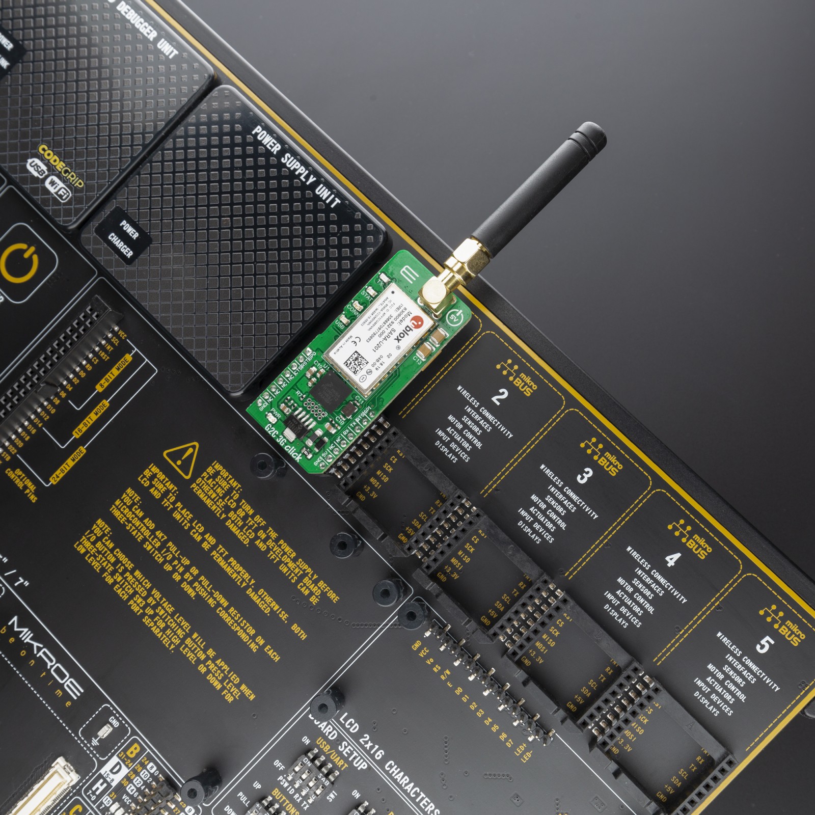
Depending on the development board you are using, you may need USB UART click, USB UART 2 click or RS232 click to connect to your PC, for development systems with no UART to USB interface available on the board. The terminal available in all MikroElektronika compilers, or any other terminal application of your choice, can be used to read the message.
mikroSDK
This click board is supported with mikroSDK – MikroElektronika Software Development Kit. To ensure proper operation of mikroSDK compliant click board demo applications, mikroSDK should be downloaded from the LibStock and installed for the compiler you are using.
For more information about mikroSDK, visit the official page.
Resources
Downloads
| Weight | 25 g |
|---|---|
| Brand | MikroElektronika |

