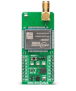
GNSS RTK 5 Click
R4,950.00 ex. VAT
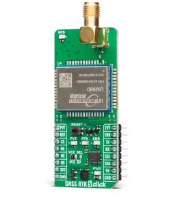
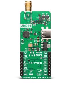
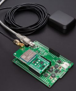
GNSS RTK 5 Click is a compact add-on board designed for demanding navigation and positioning applications. This board features the UM980, an all-constellation multifrequency RTK positioning module from Unicore, featuring the advanced NebulasIV SoC for enhanced performance. This Click board™ supports multiple satellite constellations, including GPS, BDS, GLONASS, Galileo, and more, and incorporates JamShield adaptive anti-jamming technology for reliable operation in challenging environments. Communication is enabled through a UART interface with additional features like a USB Type-C connector for standalone configuration and visual status indicators for PVT, ERR, RTK, and PPS signals. Ideal for applications such as surveying, precision agriculture, UAVs, and autonomous robotics, GNSS RTK 5 Click ensures accuracy and reliability in critical scenarios.
GNSS RTK 5 Click is fully compatible with the mikroBUS™ socket and can be used on any host system supporting the mikroBUS™ standard. It comes with the mikroSDK open-source libraries, offering unparalleled flexibility for evaluation and customization. What sets this Click board™ apart is the groundbreaking ClickID feature, enabling your host system to seamlessly and automatically detect and identify this add-on board.
NOTE: This Click board™ is compatible with Skylark® Precise Positioning Service, enabling high-precision GNSS applications. For detailed, step-by-step instructions on setting up Skylark® Precise Positioning Service, please refer to the Quick User Guide.
Stock: Lead-time applicable.
| 5+ | R4,702.50 |
| 10+ | R4,578.75 |
| 15+ | R4,455.00 |
| 20+ | R4,331.25 |
How does it work?
GNSS RTK 5 Click is based on the UM980, an all-constellation multifrequency RTK positioning module from Unicore. The UM980 uses Unicore’s NebulasIV SoC, a GNSS System-on-Chip (SoC) that combines RF-baseband integration with advanced high-precision algorithms. This SoC also includes a dual-core CPU, a high-speed floating-point processor, and a dedicated RTK co-processor, supported by 1408 channels, ensuring unparalleled signal processing capabilities. The UM980 supports many satellite constellations, including GPS, BDS, GLONASS, Galileo, QZSS, NavIC, SBAS, and L-Band, making it suitable for global high-precision applications. Its integrated JamShield adaptive anti-jamming technology further enhances signal reliability, offering faster initialization, exceptional measurement accuracy, and unmatched reliability, even in challenging environments such as dense urban landscapes and heavily shaded areas. Thanks to these advanced features, GNSS RTK 5 Click excels in many high-precision navigation and positioning scenarios like surveying and mapping, precision agriculture, unmanned aerial vehicles (UAVs), and autonomous robotics.

The UM980 and the host MCU are communicated through a UART interface, using standard UART RX and TX pins for efficient data transfer. The module defaults to a communication speed of 115200bps, allowing for seamless data exchange over AT commands. While the module also includes pins for an I2C interface, this functionality is currently unsupported in the existing firmware version. In addition to the interface pins, the board features a reset (RST) pin and a RESET button for hard resetting the module when necessary.
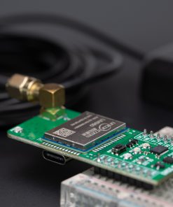
This board also includes a USB Type-C connector for USB 2.0 Full Speed 12Mbps hardware capability, allowing both power supply and configuration via a PC. This functionality is enabled by the CP2102N, a highly integrated USB-to-UART bridge, along with the MCP1826 LDO regulator, which converts the USB supply to the necessary 3.3V for the module, allowing for standalone configuration. A notable addition to the board is the inclusion of dedicated test points, among which test points 3 and 4 stand out. These represent the module’s CAN TX and RX signals, operating at LVTTL levels and offering additional functionality for specific user requirements.
The board incorporates several additional pins that enhance functionality and provide real-time status feedback. The PVT pin serves as a position, velocity, and time calculation indicator, remaining HIGH during active positioning, while the ERR pin acts as an error status indicator, showing HIGH when the module fails its self-test and LOW when it passes. Additionally, the EVT pin is used for event mark input, enabling the logging of precise GNSS time tags. Visual indicators complement these pins for improved usability: the PVT pin is linked to a green LED, and the ERR pin is connected to a red LED, providing immediate visual feedback. The board also features a blue LED to indicate the RTK feature, lighting up HIGH for an RTK fixed solution and LOW for other positioning statuses or no positioning. Furthermore, a yellow LED displays the timepulse signal (PPS), offering precise time synchronization for applications that require it.
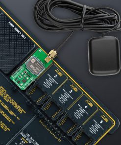
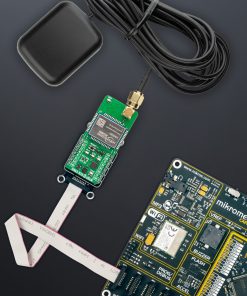
This Click board™ also features the SMA antenna connector with an impedance of 50Ω, compatible with various antennas available from MIKROE, like the GNSS L1/L5 Band Active Antenna (High and Standard precision) and others, to enhance its connectivity.
This Click board™ can operate with both 3.3V and 5V logic voltage levels selected via the VCC SEL jumper. Since the UM980 module operates at 3.3V, a logic-level translator, the TXS0108E is also used for proper operation and an accurate signal-level translation. This way, both 3.3V and 5V capable MCUs can use the communication lines properly. Also, this Click board™ comes equipped with a library containing easy-to-use functions and an example code that can be used as a reference for further development.
Specifications
Type
GPS/GNSS,RTK
Applications
Ideal for applications such as surveying, precision agriculture, UAVs, and autonomous robotics
On-board modules
UM980 – all-constellation multifrequency RTK positioning module from Unicore
Key Features
High-precision RTK positioning, module based on NebulasIV SoC, supports multifrequency and all-constellation GNSS, JamShield adaptive anti-jamming technology, UART and USB interface, visual status indicators, CAN TX/RX signals, and more
Interface
UART,USB
Feature
ClickID,Skylark® Service
Compatibility
mikroBUS™,Skylark®
Click board size
L (57.15 x 25.4 mm)
Input Voltage
3.3V or 5V,External
Pinout diagram
This table shows how the pinout on GNSS RTK 5 Click corresponds to the pinout on the mikroBUS™ socket (the latter shown in the two middle columns).
| Notes | Pin | Pin | Notes | ||||
|---|---|---|---|---|---|---|---|
| Positioning Status | PVT | 1 | AN | PWM | 16 | EVT | Event Mark |
| Reset | RST | 2 | RST | INT | 15 | ERR | Error Status |
| ID COMM | CS | 3 | CS | RX | 14 | TX | UART TX |
| NC | 4 | SCK | TX | 13 | RX | UART RX | |
| NC | 5 | MISO | SCL | 12 | SCL | I2C Clock | |
| NC | 6 | MOSI | SDA | 11 | SDA | I2C Data | |
| Power Supply | 3.3V | 7 | 3.3V | 5V | 10 | 5V | Power Supply |
| Ground | GND | 8 | GND | GND | 9 | GND | Ground |
Onboard settings and indicators
| Label | Name | Default | Description |
|---|---|---|---|
| LD1 | PWR | – | Power LED Indicator |
| LD2 | PVT | – | Positioning Status LED Indicator |
| LD3 | RTK | – | RTK Fixed LED Indicator |
| LD4 | ERR | – | Error Status LED Indicator |
| LD5 | PPS | – | Timepulse LED Indicator |
| JP1 | VCC SEL | Left | Power Voltage Level Selection 3V3/5V: Left position 3V3, Right position 5V |
| T1 | RESET | – | Reset Button |
GNSS RTK 5 Click electrical specifications
| Description | Min | Typ | Max | Unit |
|---|---|---|---|---|
| Supply Voltage | 3.3 | – | 5 | V |
| Frequency | 1.176 | – | 1.602 | GHz |
| RTK (RMS) – Horizontal +1ppm | – | 0.8 | – | cm |
| RTK (RMS) – Vertical +1ppm | – | 1.5 | – | cm |
Software Support
GNSS RTK 5 Click demo application is developed using the NECTO Studio, ensuring compatibility with mikroSDK‘s open-source libraries and tools. Designed for plug-and-play implementation and testing, the demo is fully compatible with all development, starter, and mikromedia boards featuring a mikroBUS™ socket.
Example Description
This example demonstrates the use of GNSS RTK 5 Click by reading and displaying the GNSS coordinates.
Key Functions
gnssrtk5_cfg_setupConfig Object Initialization function.gnssrtk5_initInitialization function.gnssrtk5_cmd_runThis function parses the GGA data from the read response buffer.gnssrtk5_parse_ggaThis function parses the GGA data from the read response buffer.gnssrtk5_generic_readThis function reads a desired number of data bytes by using UART serial interface.
Application Init
Initializes the driver, resets the Click board, reads the module version and config, and enables the NMEA GNGGA message output.
Application Task
Reads the received data, parses the NMEA GGA info from it, and once it receives the position fix it will start displaying the coordinates on the USB UART.
Application Output
This Click board can be interfaced and monitored in two ways:
- Application Output – Use the “Application Output” window in Debug mode for real-time data monitoring. Set it up properly by following this tutorial.
- UART Terminal – Monitor data via the UART Terminal using a USB to UART converter. For detailed instructions, check out this tutorial.
Additional Notes and Information
The complete application code and a ready-to-use project are available through the NECTO Studio Package Manager for direct installation in the NECTO Studio. The application code can also be found on the MIKROE GitHub account.
Resources
Downloads
| Weight | 23 g |
|---|---|
| Brand | MikroElektronika |