GNSS RTK 4 Click
R3,350.00 ex. VAT
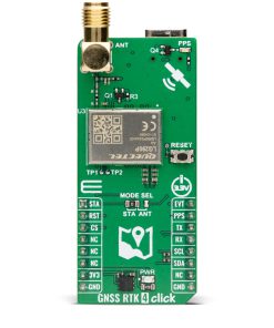
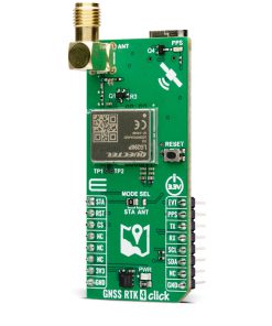
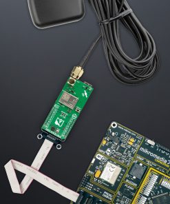
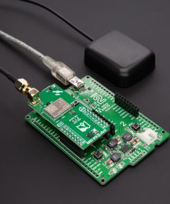
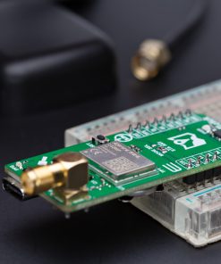
GNSS RTK 4 Click is a compact add-on board designed for high-precision GNSS positioning with real-time kinematics (RTK) support. This board features the LG290P, a quad-band GNSS module from Quectel, capable of receiving signals from GPS, GLONASS, Galileo, BDS, QZSS, and NavIC while using SBAS for enhanced accuracy. This board supports multi-mode RTK algorithms with fast convergence times and high accuracy, interference detection, and integrity monitoring, ensuring sub-meter positioning in demanding environments. It features UART and I2C interfaces, a USB Type-C port for standalone configuration, and a backup battery option for continuous operation. GNSS RTK 4 Click is ideal for applications requiring precise positioning, including autonomous navigation, UAVs, intelligent robotics, surveying, and precision agriculture.
GNSS RTK 4 Click is fully compatible with the mikroBUS™ socket and can be used on any host system supporting the mikroBUS™ standard. It comes with the mikroSDK open-source libraries, offering unparalleled flexibility for evaluation and customization. What sets this Click board™ apart is the groundbreaking ClickID feature, enabling your host system to seamlessly and automatically detect and identify this add-on board.
Stock: Lead-time applicable.
| 5+ | R3,182.50 |
| 10+ | R3,098.75 |
| 15+ | R3,015.00 |
| 20+ | R2,931.25 |
How does it work?
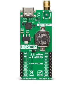
GNSS RTK 4 Click is based on the LG290P, a high-precision GNSS module from Quectel designed for quad-band RTK positioning and multi-constellation support. This module simultaneously receives signals from GPS, GLONASS, Galileo, BDS, QZSS, and NavIC while utilizing SBAS systems (WAAS, EGNOS, BDSBAS, MSAS, GAGAN, and SDCM) to enhance signal accuracy. Its advanced RTK algorithm enables rapid convergence and reliable sub-meter precision, making it ideal for precise navigation in urban areas, industrial applications, and challenging environments with dense foliage.

To ensure optimal signal reception in electromagnetically complex environments, the LG290P integrates interference detection and elimination technologies, effectively mitigating multiple narrow-band interference sources. The module also supports multi-mode RTK algorithms, offering fast response times in high-precision positioning scenarios. Beyond positioning accuracy, the LG290P includes Secure Boot, on-chip storage with ECC verification, and integrity monitoring, ensuring firmware security and operational reliability. These features make it well-suited for autonomous navigation, UAVs, intelligent robotics, precision agriculture, surveying, and mining applications.
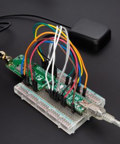
This Click board™ uses the UART interface as a main communication interface with an additional I2C interface with frequencies up to 400kHz for user-specific cases. It is important to note that firmware does not currently support this interface. Besides, the module also provides an additional UART interface via test points TP1 and TP2 that supports standard NMEA messages and debugging data. This board also includes a USB Type-C connector for USB 2.0 Full Speed capability, allowing for configuration via a PC. This functionality is enabled by the CP2102N, a USB-to-UART bridge, along with the NCP1117 LDO regulator, which converts the USB supply to the necessary 3.3V for the module, allowing for standalone configuration.
In case of a power failure, the module can switch to a backup battery, ensuring continuous operation of the real-time clock (RTC) and battery-backed RAM. This preserves critical data and enables faster warm and hot starts. If no battery is present, the backup function is powered via the 3.3V rail of the mikroBUS™ socket.
Besides the interface, the GNSS RTK 4 Click includes several pins for additional module control. The EVT pin provides event inputs with adjustable frequency and polarity, allowing for customizable input control. The STA pin indicates the RTK positioning status, where a HIGH signal signifies that the module is in RTK fix mode, while a LOW signal indicates the module has exited RTK fix mode. This function is available if the MODE SEL jumper is set to the STA position, the default configuration. Alternatively, the STA pin controls the external LNA or active antenna power supply if set to the ANT position. It is important to note that firmware has not yet supported this ANT function. Additionally, the RST pin allows for resetting the module, a function that can also be performed using the onboard RESET button.
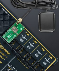
The GNSS RTK 4 Click has an SMA antenna connector, marked ANT, for connecting an appropriate antenna, also offered by MIKROE, such as a GNSS L1/L5 Active External Antenna. This antenna is an excellent choice for all GNSS applications supporting L1 and L5 band frequencies. Also, the GNSS RTK 4 Click includes a yellow PPS LED indicator, which emits a synchronized pulse signal from the LG290P once per second.
This Click board™ can be operated only with a 3.3V logic voltage level. The board must perform appropriate logic voltage level conversion before using MCUs with different logic levels. Also, it comes equipped with a library containing functions and an example code that can be used as a reference for further development.
Specifications
Type
GPS/GNSS
Applications
Ideal for applications requiring precise positioning, including autonomous navigation, UAVs, intelligent robotics, surveying, and precision agriculture
On-board modules
LG290P – quad-band and multi-constellation GNSS module from Quectel
Key Features
High-Precision GNSS module, multi-constellation support, enhanced accuracy, multi-mode RTK algorithms, interference detection and integrity monitoring, UART, I2C, and USB interfaces, backup battery support, and more
Interface
I2C,UART,USB
Feature
ClickID
Compatibility
mikroBUS™
Click board size
L (57.15 x 25.4 mm)
Input Voltage
3.3V
Pinout diagram
This table shows how the pinout on GNSS RTK 4 Click corresponds to the pinout on the mikroBUS™ socket (the latter shown in the two middle columns).
| Notes | Pin | Pin | Notes | ||||
|---|---|---|---|---|---|---|---|
| RTK Positioning Status | STA | 1 | AN | PWM | 16 | EVT | Event Triggering Signal |
| Reset | RST | 2 | RST | INT | 15 | PPS | Timepulse Signal |
| ID COMM | CS | 3 | CS | RX | 14 | TX | UART TX |
| NC | 4 | SCK | TX | 13 | RX | UART RX | |
| NC | 5 | MISO | SCL | 12 | SCL | I2C Clock | |
| NC | 6 | MOSI | SDA | 11 | SDA | I2C Data | |
| Power Supply | 3.3V | 7 | 3.3V | 5V | 10 | NC | |
| Ground | GND | 8 | GND | GND | 9 | GND | Ground |
Onboard settings and indicators
| Label | Name | Default | Description |
|---|---|---|---|
| LD1 | PWR | – | Power LED Indicator |
| LD2 | PPS | – | Timepulse LED Indicator |
| JP1 | MODE SEL | Left | Mode Selection STA/ANT: Left position STA, Right position ANT |
| T1 | RESET | – | Reset Button |
GNSS RTK 4 Click electrical specifications
| Description | Min | Typ | Max | Unit |
|---|---|---|---|---|
| Supply Voltage | – | 3.3 | – | V |
| Frequency | 1176 | – | 1575 | MHz |
| Sensitivity – Acquisition | – | -145 | – | dBm |
| TTFF – Cold Start | – | 28 | – | sec |
Software Support
GNSS RTK 4 Click demo application is developed using the NECTO Studio, ensuring compatibility with mikroSDK‘s open-source libraries and tools. Designed for plug-and-play implementation and testing, the demo is fully compatible with all development, starter, and mikromedia boards featuring a mikroBUS™ socket.
Example Description
This example demonstrates the use of GNSS RTK 4 Click by reading and displaying the GNSS coordinates.
Key Functions
gnssrtk4_cfg_setupThis function initializes Click configuration structure to initial values.gnssrtk4_initThis function initializes all necessary pins and peripherals used for this Click board.gnssrtk4_generic_readThis function reads a desired number of data bytes by using UART serial interface.gnssrtk4_parse_ggaThis function parses the GGA data from the read response buffer.gnssrtk4_reset_deviceThis function resets the device by toggling the RST pin.
Application Init
Initializes the driver and logger.
Application Task
Reads the received data, parses the NMEA GGA info from it, and once it receives the position fix it will start displaying the coordinates on the USB UART.
Application Output
This Click board can be interfaced and monitored in two ways:
- Application Output – Use the “Application Output” window in Debug mode for real-time data monitoring. Set it up properly by following this tutorial.
- UART Terminal – Monitor data via the UART Terminal using a USB to UART converter. For detailed instructions, check out this tutorial.
Additional Notes and Information
The complete application code and a ready-to-use project are available through the NECTO Studio Package Manager for direct installation in the NECTO Studio. The application code can also be found on the MIKROE GitHub account.
Resources
Downloads
| Weight | 24 g |
|---|---|
| Brand | MikroElektronika |