How does it work?
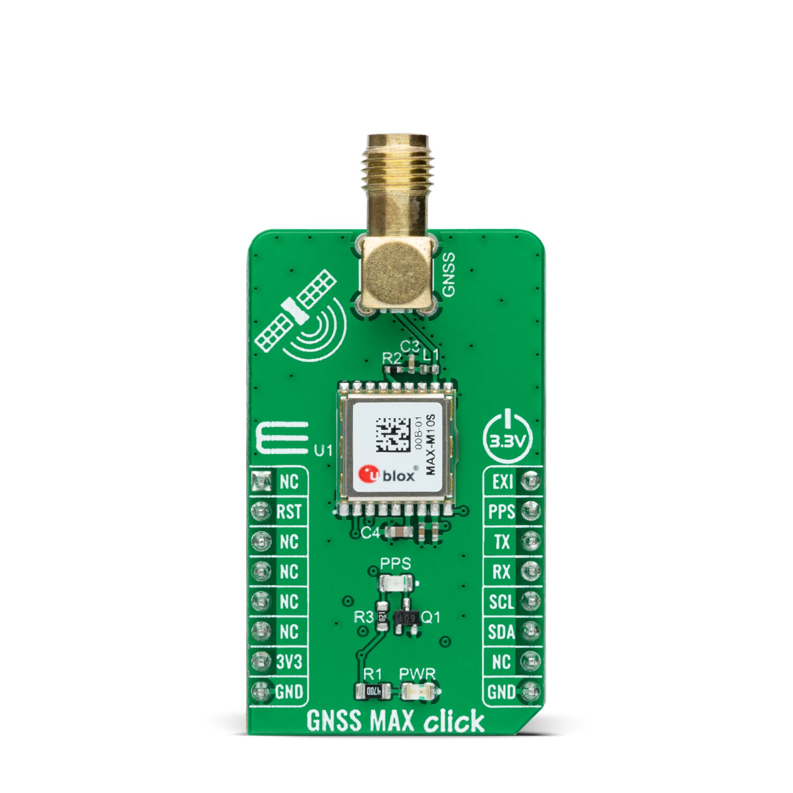
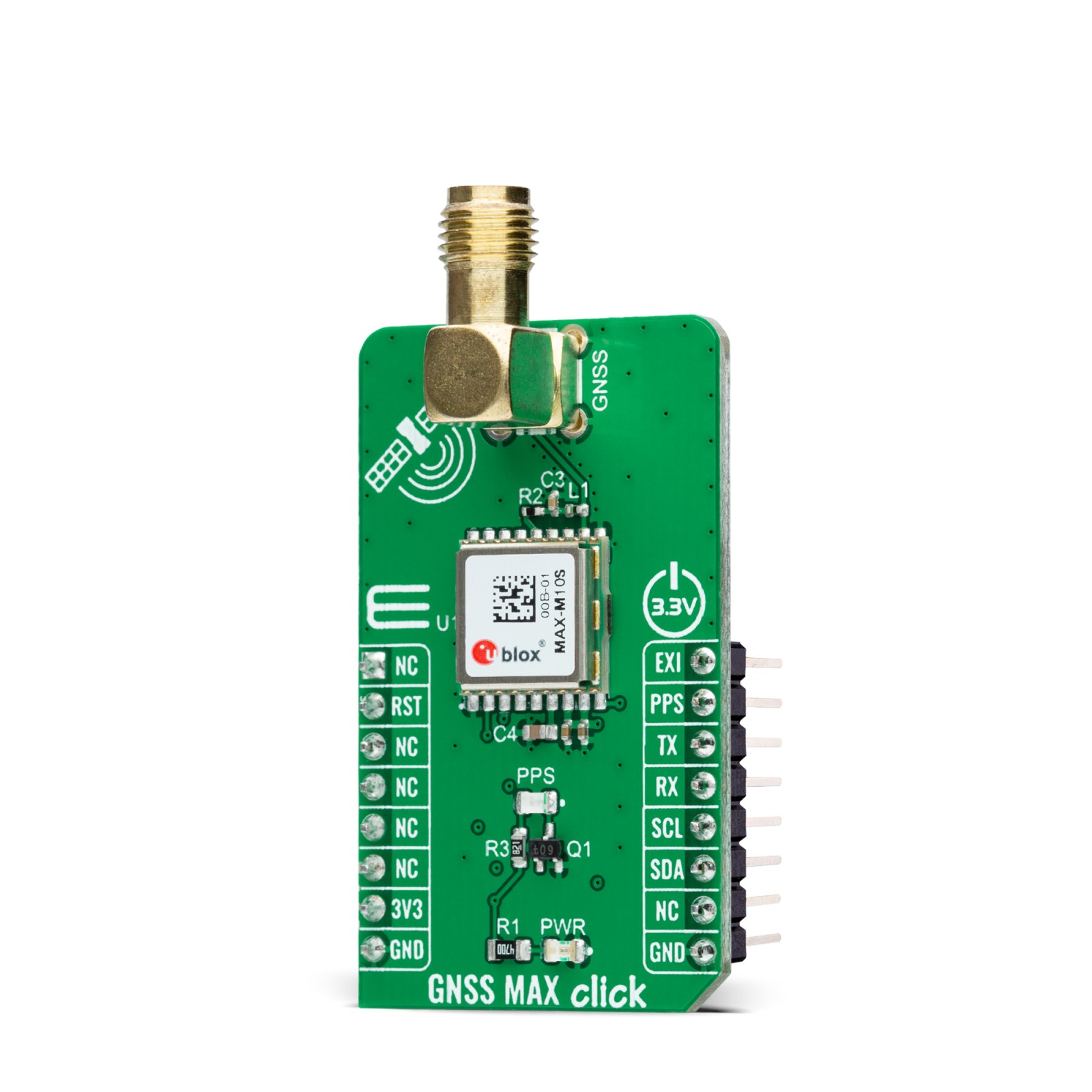
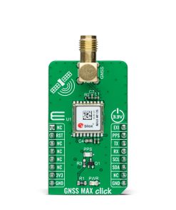
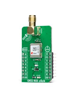
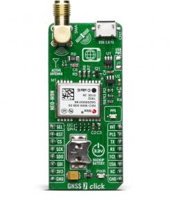
GNSS MAX Click as its foundation uses the MAX-M10S (MAX-M10S-00B-01), a high-performance GNSS module from u-blox. The MAX-M10S features the u-blox M10 standard precision GNSS platform and provides exceptional sensitivity and acquisition times for all L1 GNSS signals. It also supports concurrent reception of up to four GNSS (GPS, GLONASS, Galileo, and BeiDou), maximizing position availability, particularly under challenging conditions such as in deep urban canyons. The MAX-M10S offers high sensitivity and minimal acquisition times while maintaining low system power.
The MAX-M10S module integrates an LNA followed by a SAW filter in the RF path for maximum sensitivity. Also, it detects jamming and spoofing attempts and reports them to the host so that the system can react to such events. Advanced filtering algorithms mitigate the impact of RF interference and jamming, thus enabling the product to operate as intended. The u-blox Super-S technology offers great RF sensitivity that improves the dynamic position accuracy by up to 25% with small antennas or in a non-line-of-sight scenario.
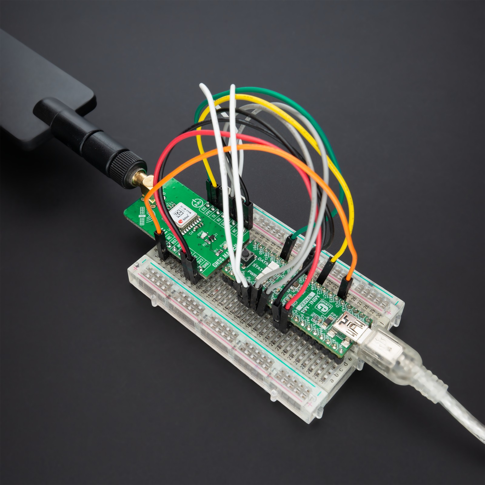
This Click board™ comes with a configurable host interface that allows communication with MCU using the selected interface. The MAX-M10S can communicate with MCU using the UART interface with commonly used UART RX and TX pins as its default communication protocol operating at 9600bps to transmit and exchange data with the host MCU or using the I2C interface. I2C interface is compatible with the Fast-Mode allowing a maximum bit rate of 400kbit/s.
In addition to these features, it also uses several mikroBUS™ pins. An active-low reset signal routed on the RST pin of the mikroBUS™ socket activates a hardware reset of the system, while the EXT pin routed to the PWM pin on the mikroBUS™ socket represents an external interrupt used for the module Wake-Up function. It also uses a PPS signal routed on the INT pin of the mikroBUS™ socket alongside a blue LED indicator marked as STATUS used for time pulse signal information and indication.
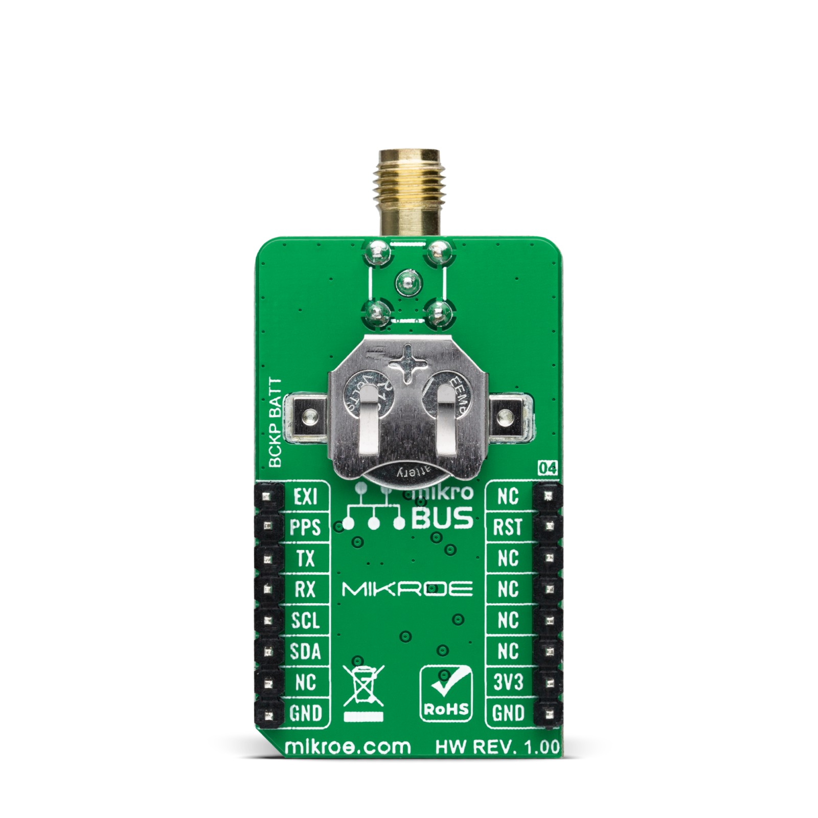
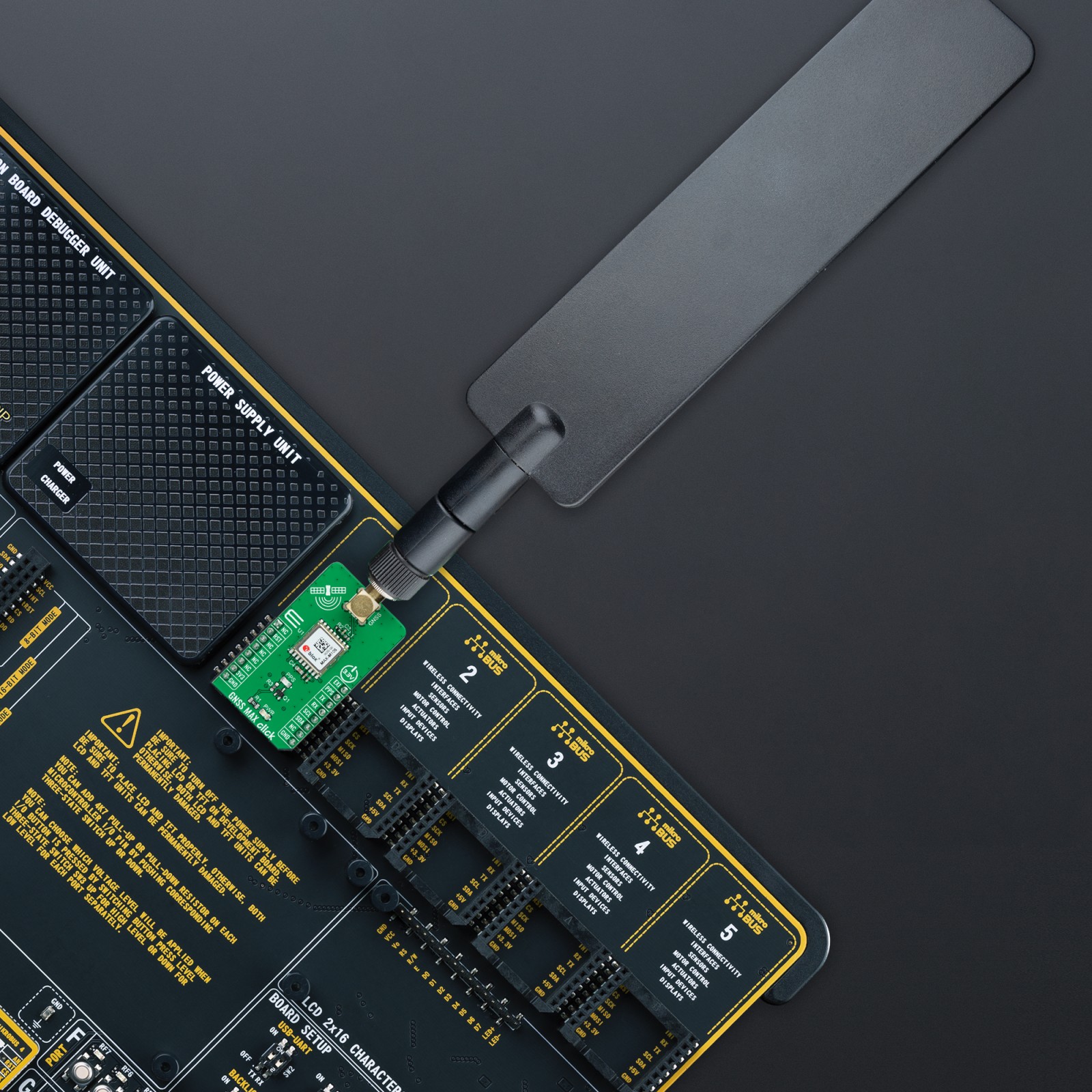
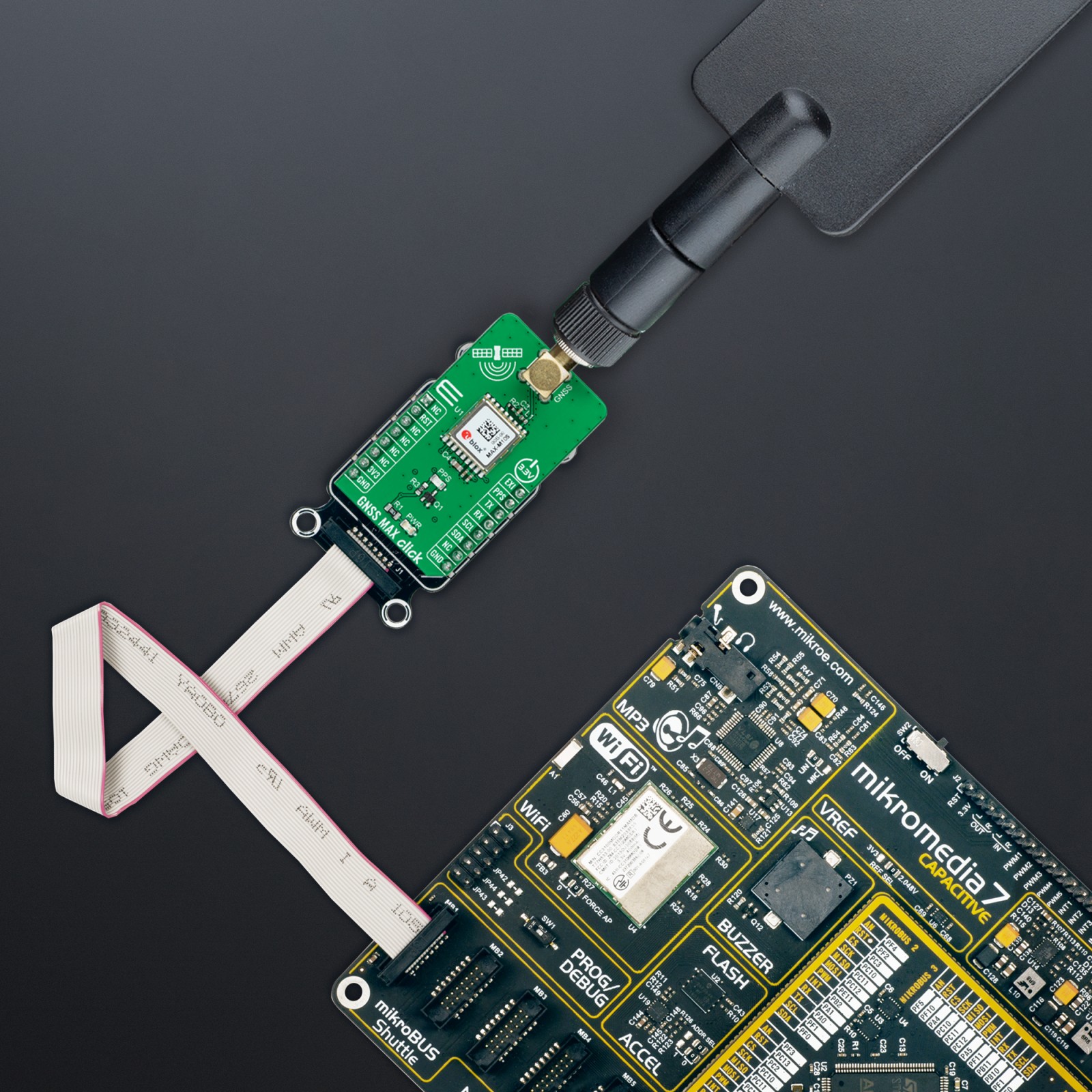
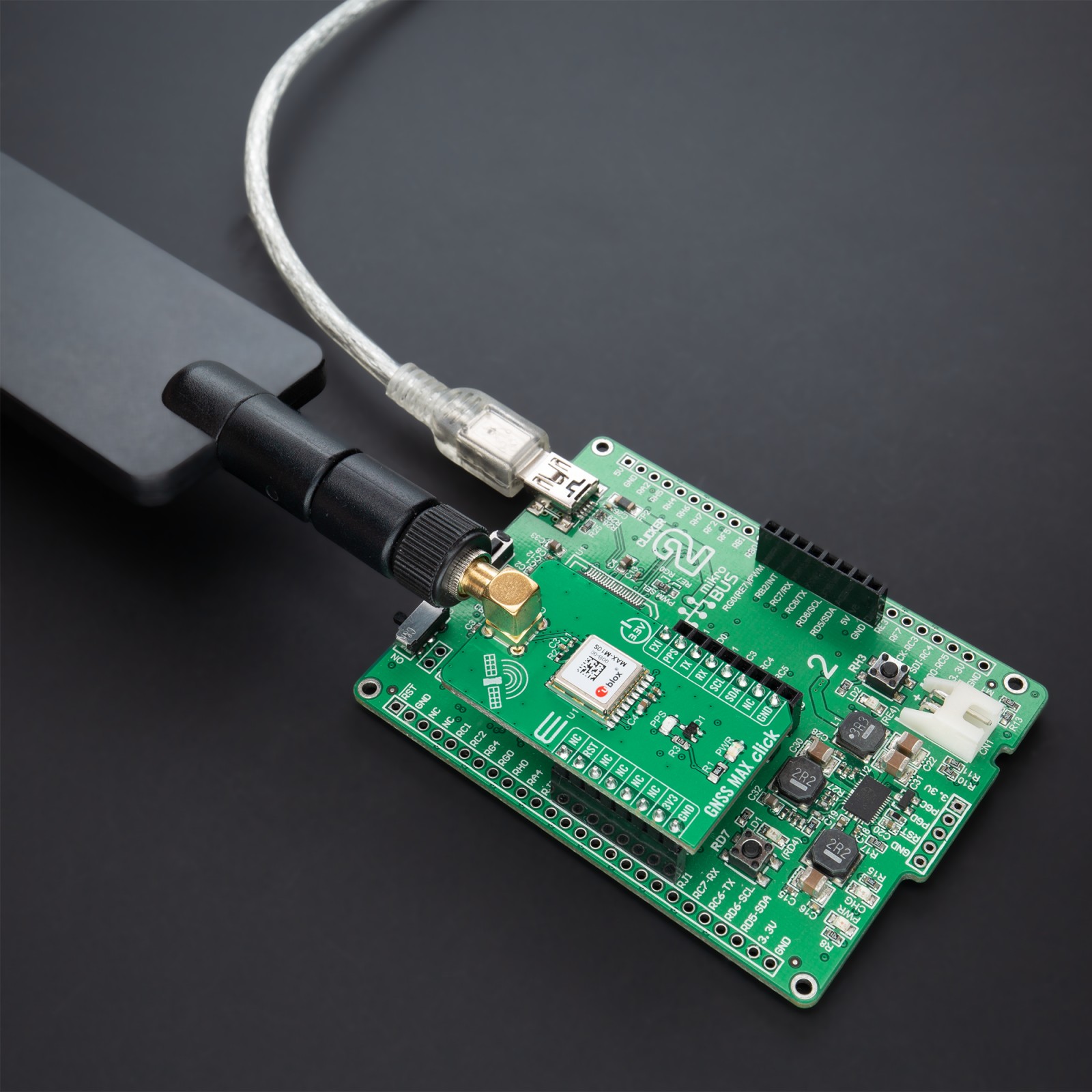
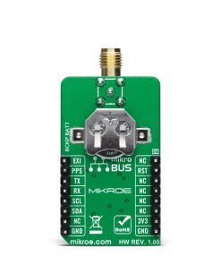
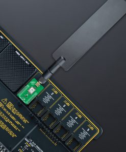
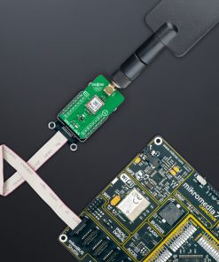
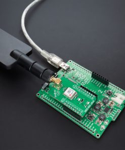
GNSS MAX Click possesses the SMA antenna connector on which an appropriate antenna connects that Mikroe has in its offer for improved range and received signal strength. Also, in the case of the primary supply failure, the module can use a backup supply voltage from a connected battery if you need the Click board™ to be a standalone device.
This Click board™ can be operated only with a 3.3V logic voltage level. The board must perform appropriate logic voltage level conversion before using MCUs with different logic levels. However, the Click board™ comes equipped with a library containing functions and an example code that can be used, as a reference, for further development.
Specifications
Type
GPS/GNSS
Applications
Can be used for professional (industrial and consumer) applications such as asset trackers
On-board modules
MAX-M10S – standard precision GNSS module from u-blox
Key Features
Low power consumption, maximum position availability with concurrent reception of 4 GNSS, proven excellent performance, advanced jamming and spoofing detection, selectable interface, and more
Interface
I2C,UART
Feature
No ClickID
Compatibility
mikroBUS™
Click board size
M (42.9 x 25.4 mm)
Input Voltage
3.3V
Pinout diagram
This table shows how the pinout on GNSS MAX Click corresponds to the pinout on the mikroBUS™ socket (the latter shown in the two middle columns).
Onboard settings and indicators
Label | Name | Default | Description |
---|---|---|---|
LD1 | PWR | – | Power LED Indicator |
LD2 | PPS | – | Time Pulse LED Indicator |
GNSS MAX Click electrical specifications
Description | Min | Typ | Max | Unit |
---|---|---|---|---|
Supply Voltage | – | 3.3 | – | V |
Horizontal Position Accuracy | – | 1.5 | – | m |
Tracking & Navigation Sensitivity | – | -167 | – | dBm |
Operating Temperature Range | -40 | +25 | +85 | °C |
Software Support
We provide a library for the GNSS MAX Click as well as a demo application (example), developed using MikroElektronika compilers. The demo can run on all the main MikroElektronika development boards.
Package can be downloaded/installed directly from NECTO Studio Package Manager(recommended way), downloaded from our LibStock™ or found on Mikroe github account.
Library Description
This library contains API for GNSSMAX Click driver.
Key functions:
gnssmax_generic_read
– GNSS MAX data reading function.gnssmax_reset
– GNSS MAX reset function.gnssmax_get_pps
– GNSS MAX reads timestamp pin state.
Examples description
This example showcases device abillity to read data outputed from device and show it’s coordinates and altitude when connected.
void application_task ( void ) { gnssmax_process(); err_t error_flag = gnssmax_element_parser( RSP_GNGGA, RSP_GNGGA_LATITUDE_ELEMENT, latitude_data ); error_flag |= gnssmax_element_parser( RSP_GNGGA, RSP_GNGGA_LONGITUDE_ELEMENT, longitude_data ); error_flag |= gnssmax_element_parser( RSP_GNGGA, RSP_GNGGA_ALTITUDE_ELEMENT, altitude_data ); if ( error_flag == GNSSMAX_OK ) { if ( last_error_flag != GNSSMAX_OK ) { log_printf( &logger, "rn" ); } log_printf( &logger, ">Latitude:rn - deg: %.2s rn - min: %srn", latitude_data, &latitude_data[ 2 ] ); log_printf( &logger, ">Longitude:rn - deg: %.3s rn - min: %srn", longitude_data, &longitude_data[ 3 ] ); log_printf( &logger, ">Altitude:rn - %smrn", altitude_data ); log_printf( &logger, "----------------------------------------rn" ); } else if ( error_flag < GNSSMAX_ERROR ) { if ( last_error_flag == GNSSMAX_OK ) { log_printf( &logger, "Waiting for data " ); } log_printf( &logger, "." ); } if ( error_flag != GNSSMAX_ERROR ) { last_error_flag = error_flag; gnssmax_clear_app_buf( ); } }
The full application code, and ready to use projects can be installed directly from NECTO Studio Package Manager(recommended way), downloaded from our LibStock™ or found on Mikroe github account.
Other mikroE Libraries used in the example:
- MikroSDK.Board
- MikroSDK.Log
- Click.GNSSMAX
Additional notes and informations
Depending on the development board you are using, you may need USB UART click, USB UART 2 click or RS232 click to connect to your PC, for development systems with no UART to USB interface available on the board. The terminal available in all MikroElektronika compilers, or any other terminal application of your choice, can be used to read the message.
mikroSDK
This Click board™ is supported with mikroSDK – MikroElektronika Software Development Kit. To ensure proper operation of mikroSDK compliant Click board™ demo applications, mikroSDK should be downloaded from the LibStock and installed for the compiler you are using.
For more information about mikroSDK, visit the official page.