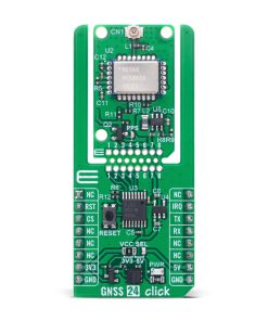
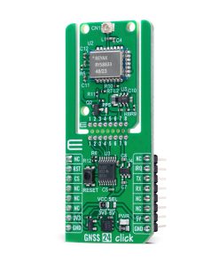
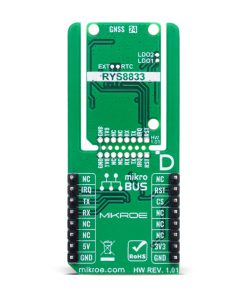
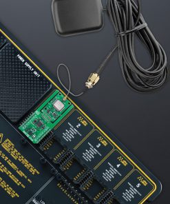
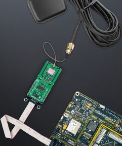
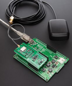
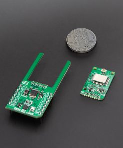
GNSS 24 Click is a compact add-on board designed for precise and reliable global positioning. This board features the RYS8833, a multi-GNSS module from REYAX, powered by the high-performance SONY CXD5605AGF engine. Supporting GPS, GLONASS, Galileo, BeiDou, SBAS, and QZSS systems, it delivers outstanding sensitivity down to -167dBm and operates on 1.561GHz, 1.575GHz, and 1.602GHz frequencies. The module includes integrated digital noise filters, spectrum analyzer, SAW filter, LNA, TCXO, and communicates via UART. It also supports MIKROE’s Click Snap format for flexible integration. GNSS 24 Click is ideal for navigation, asset tracking, and other location-based applications requiring accurate and efficient GNSS data.
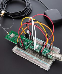
GNSS 24 Click is fully compatible with the mikroBUS™ socket and can be used on any host system supporting the mikroBUS™ standard. It comes with the mikroSDK open-source libraries, offering unparalleled flexibility for evaluation and customization. What sets this Click board™ apart is the groundbreaking ClickID feature, enabling your host system to seamlessly and automatically detect and identify this add-on board, alongside a Click Snap feature introducing a new level of flexibility and ease of use.
 Accel Click
1 × R345.00
Accel Click
1 × R345.00 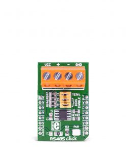 RS485 Click 5V
1 × R230.00
RS485 Click 5V
1 × R230.00 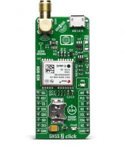 GNSS 7 Click
1 × R710.00
GNSS 7 Click
1 × R710.00 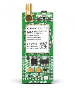 GSM2 Click
1 × R945.00
GSM2 Click
1 × R945.00 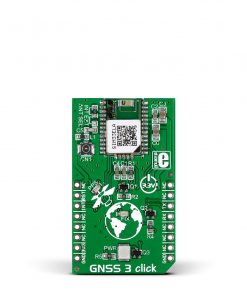 GNSS 3 Click
1 × R500.00
GNSS 3 Click
1 × R500.00