-
×
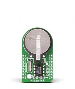 RTC 2 Click
1 ×
RTC 2 Click
1 × R455.00R409.50 -
×
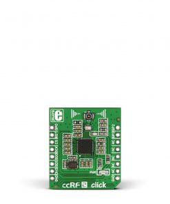 ccRF2 Click
1 ×
ccRF2 Click
1 × R785.00R706.50 -
×
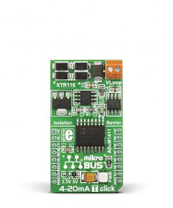 4-20mA T Click
1 × R395.00
4-20mA T Click
1 × R395.00 -
×
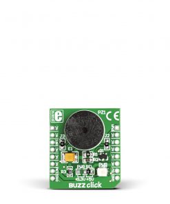 BUZZ Click
1 × R115.00
BUZZ Click
1 × R115.00 -
×
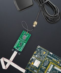
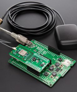
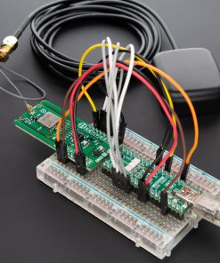
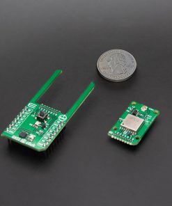
 GSM/GNSS Click
2 ×
GSM/GNSS Click
2 × R1,650.00R1,485.00 -
×
 tRF Click
1 ×
tRF Click
1 × R1,050.00R945.00 -
×
 4-20mA R Click
1 × R470.00
4-20mA R Click
1 × R470.00 -
×
 BEE Click
1 ×
BEE Click
1 × R785.00R706.50 -
×
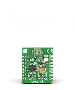 DAC Click
1 ×
DAC Click
1 × R400.00R360.00 -
×
 Alcohol 3 Click
1 ×
Alcohol 3 Click
1 × R695.00R625.50 -
×
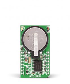 RTC Click
2 ×
RTC Click
2 × R385.00R346.50 -
×
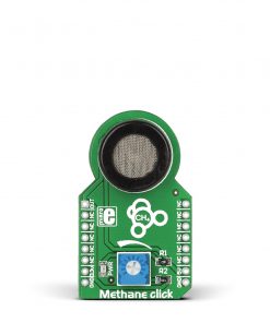 METHANE Click
1 ×
METHANE Click
1 × R330.00R297.00 -
×
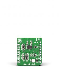 Accel Click
1 ×
Accel Click
1 × R345.00R310.50 -
×
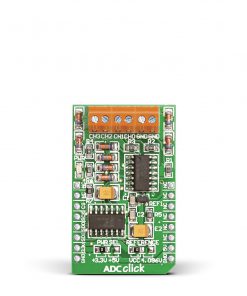 ADC Click
1 ×
ADC Click
1 × R530.00R477.00 -
×
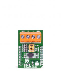 RS485 Click 5V
1 × R230.00
RS485 Click 5V
1 × R230.00 -
×
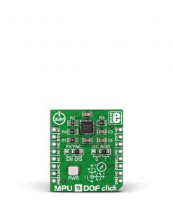 MPU 9DOF Click
1 × R535.00
MPU 9DOF Click
1 × R535.00
Subtotal: R10,245.50