How does it work?
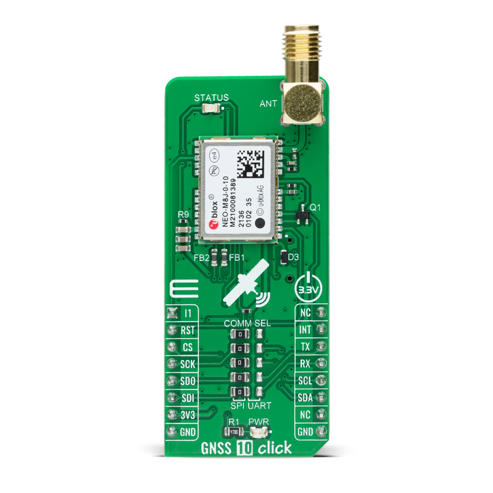
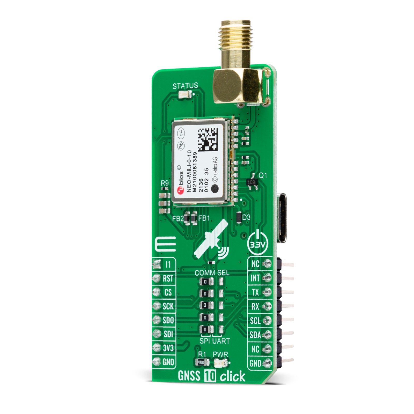
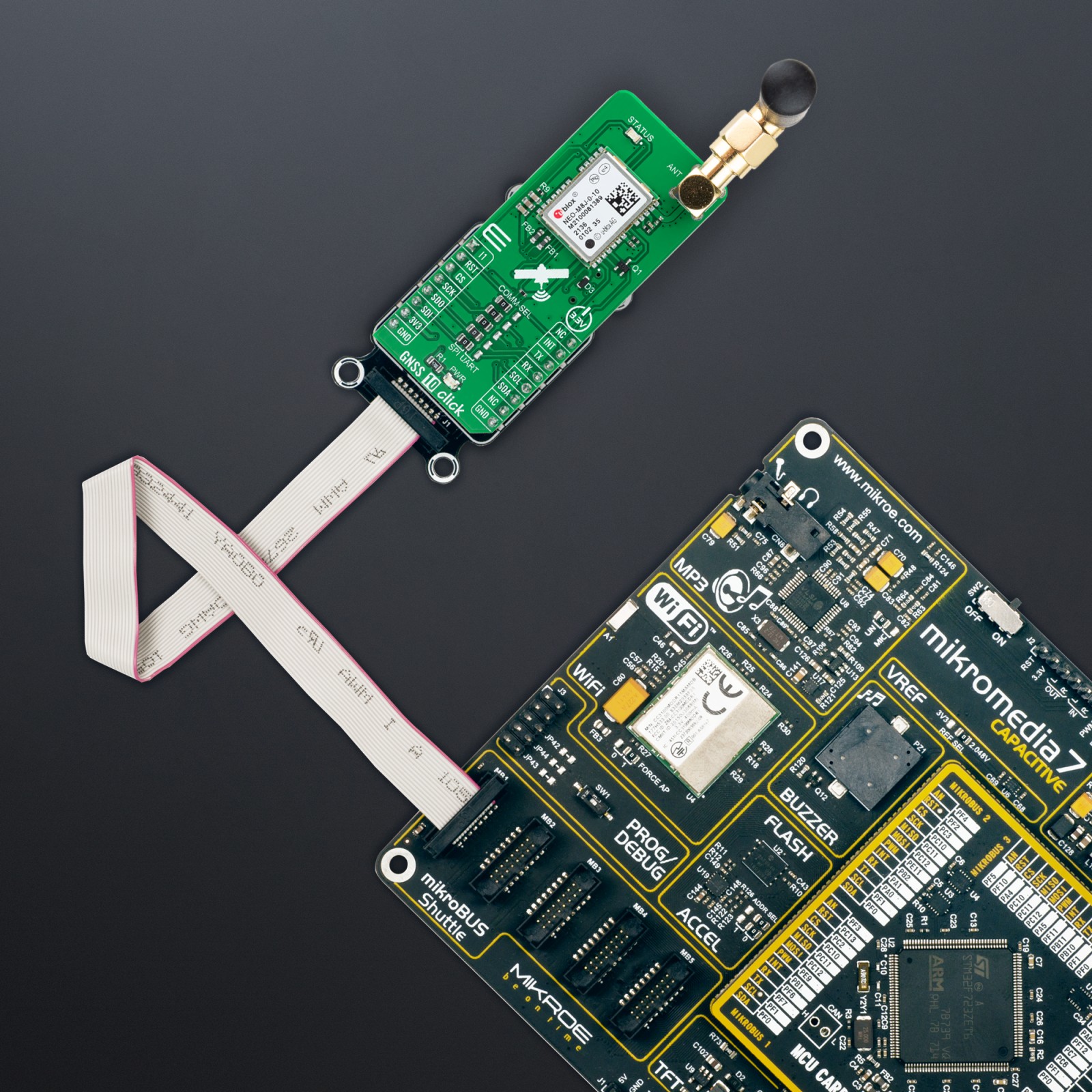
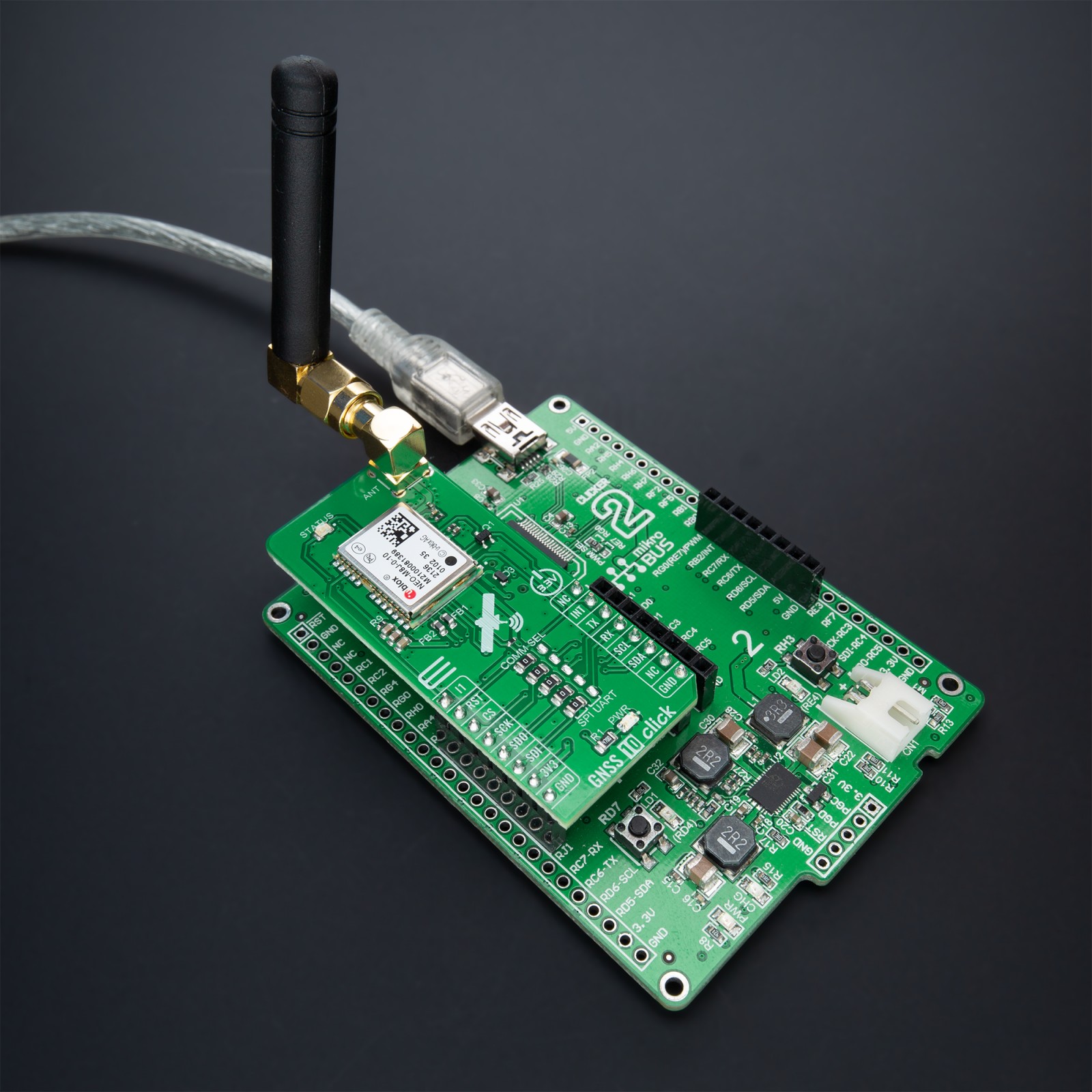
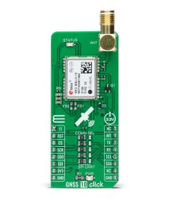
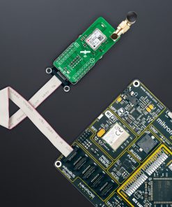
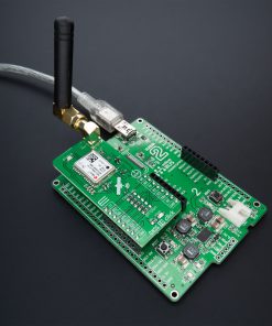
GNSS 10 Click as its foundation uses the NEO-M8J, a high-performance GNSS module from u-blox. This module is built on the high-performing M8 GNSS engine in the industry-proven NEO form factor. It utilizes concurrent reception of up to three GNSS systems (GPS/Galileo together with BeiDou or GLONASS), recognizes multiple constellations simultaneously, and provides outstanding positioning accuracy in scenarios where urban canyon or weak signals are involved. The NEO-M8J offers high sensitivity and minimal acquisition times while maintaining low system power.
For even better and faster positioning improvement, the NEO-M8J supports the augmentation of QZSS, GAGAN, and IMES together with WAAS, EGNOS, and MSAS. The future-proof NEO-M8J includes an internal Flash that allows future firmware updates, making it ideally suited to industrial and automotive applications. It also supports message integrity protection, geofencing, and spoofing detection with configurable interface settings to fit customer applications easily.
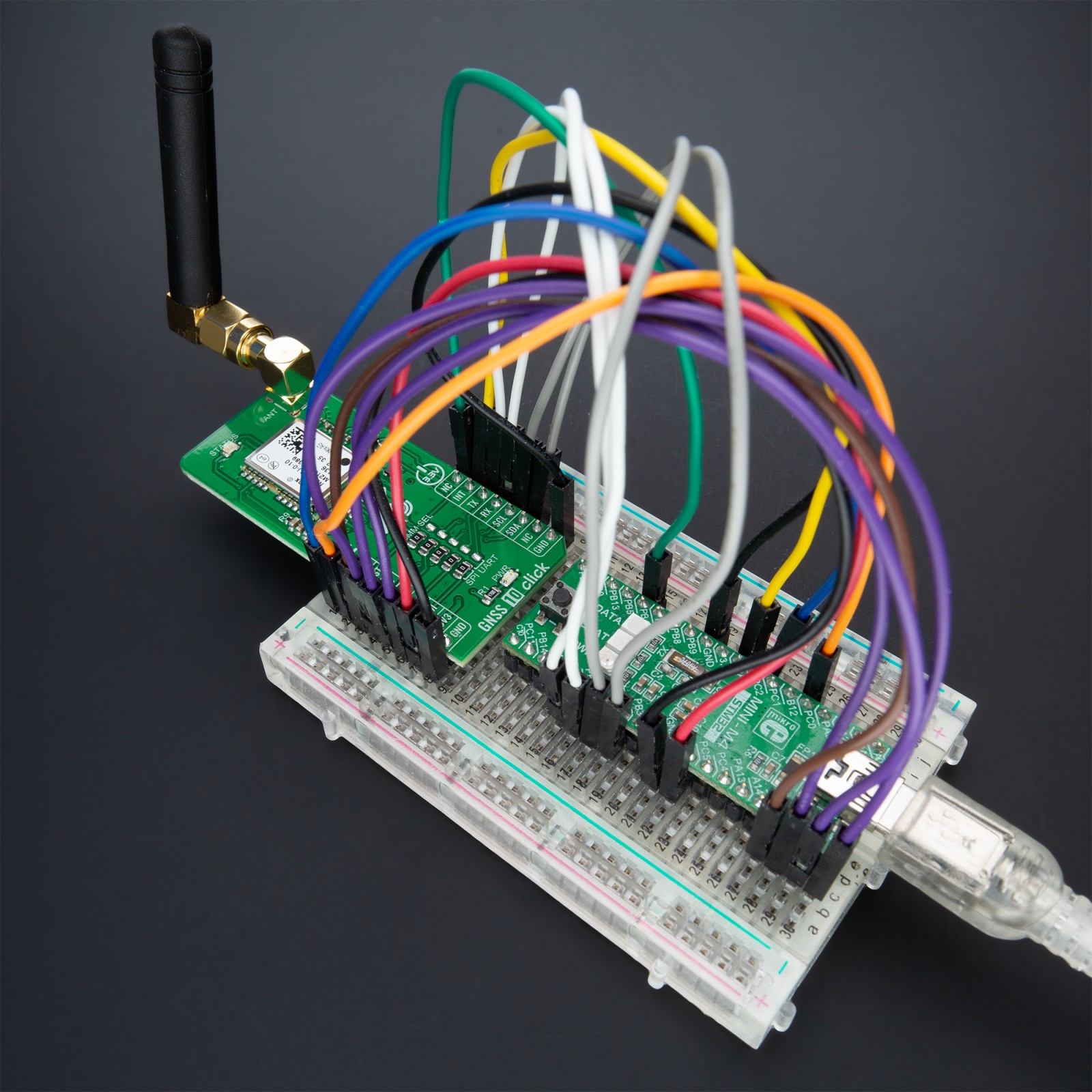
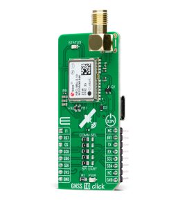
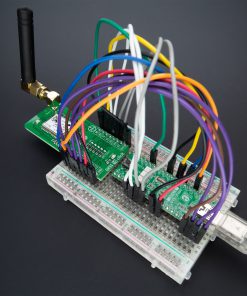
This Click board™ comes with a configurable host interface, allowing to choose communication with MCU using the UART, SPI, or I2C interface. The interface selection can be performed by positioning SMD jumpers labeled as COMM SEL to an appropriate position. Note that all the jumpers’ positions must be on the same side, or the Click board™ may become unresponsive. In this case, the SPI represents its default communication protocol. When selecting the SPI communication, it is mandatory to leave the jumper to DSEL populated, the first jumper at the top of the COMM SEL jumpers, to configure the interface pins as SPI. SPI interface can’t be used simultaneously with UART/I2C. To activate the UART/I2C selection, the jumper labeled as DSEL must be unpopulated.
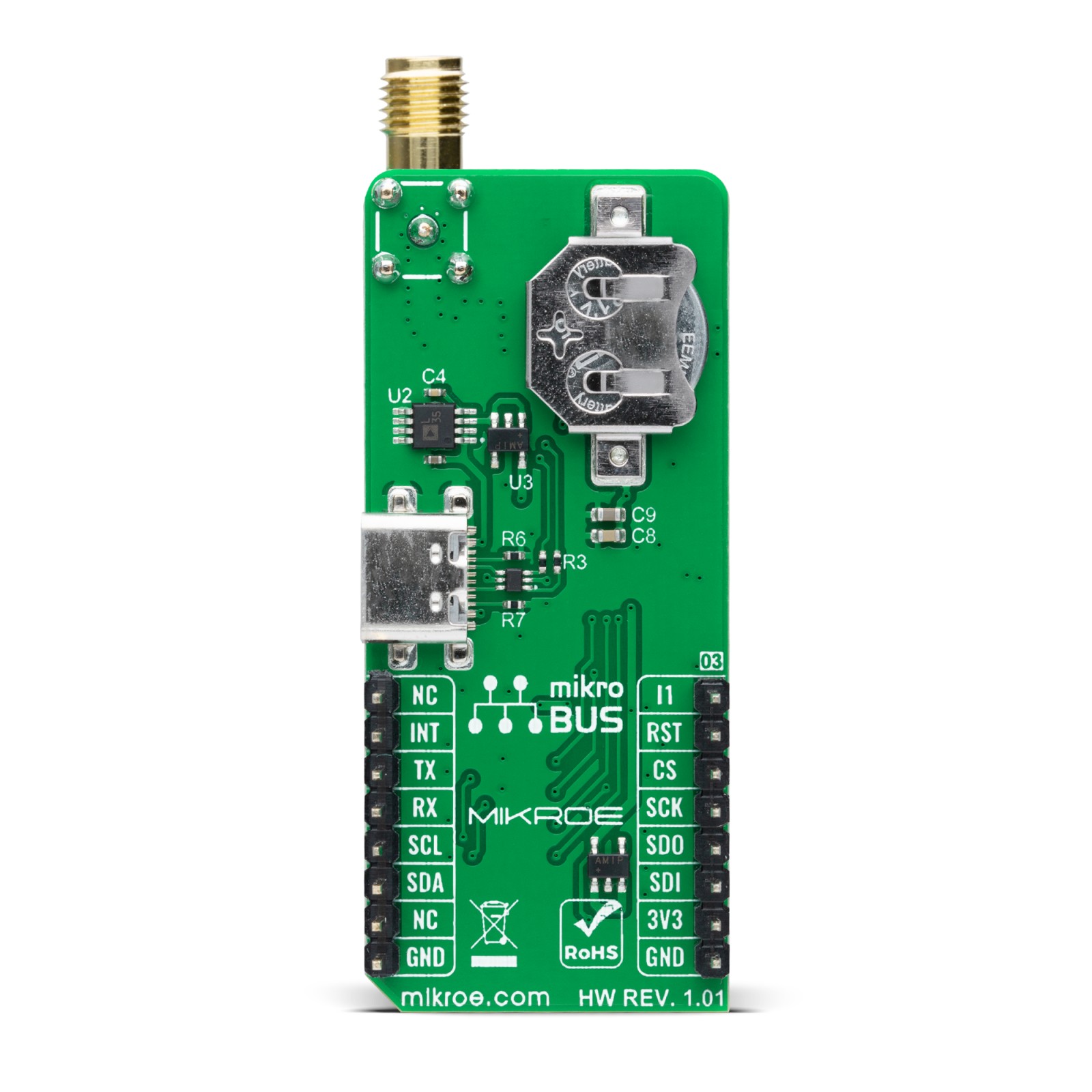
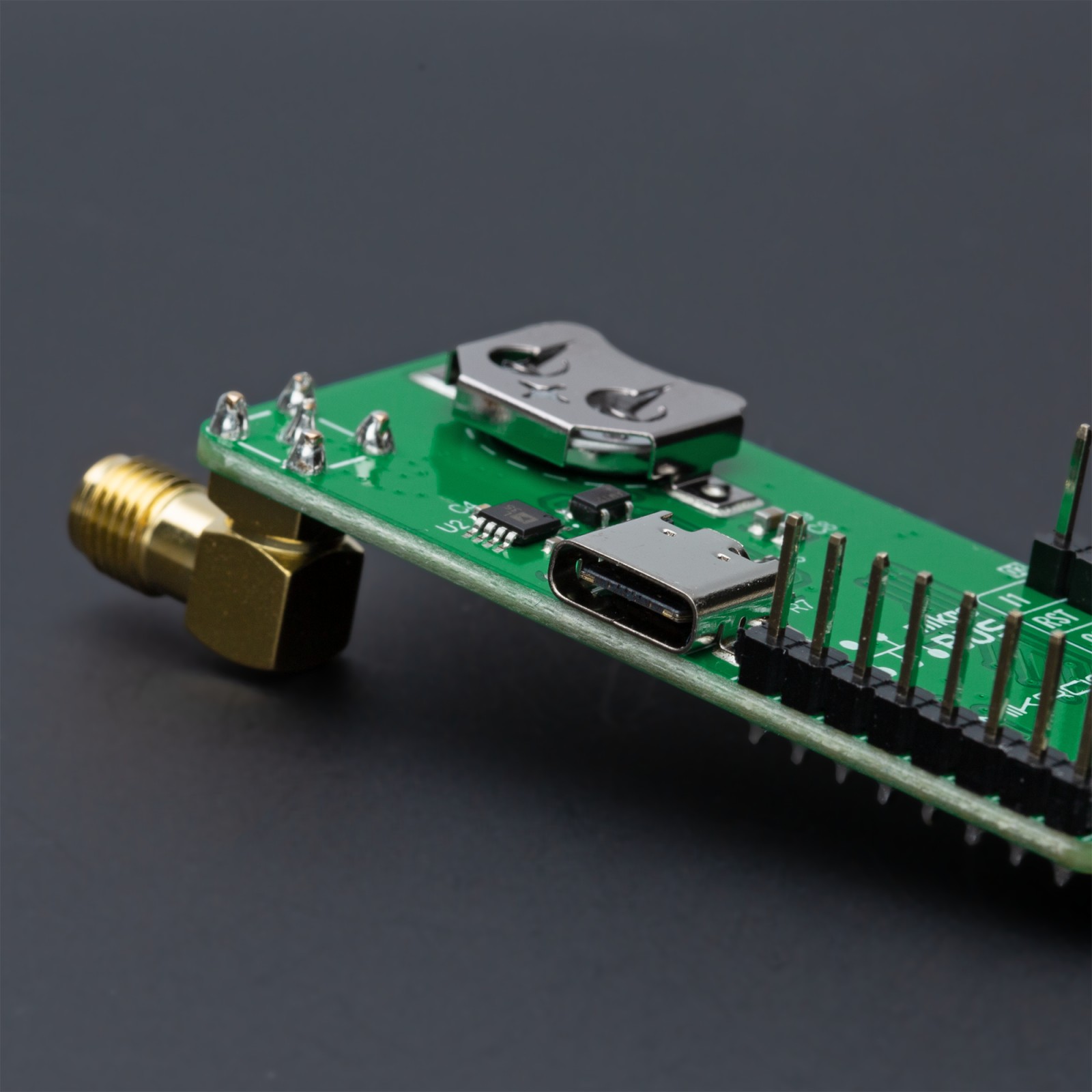
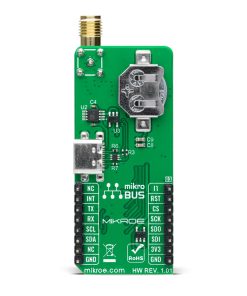
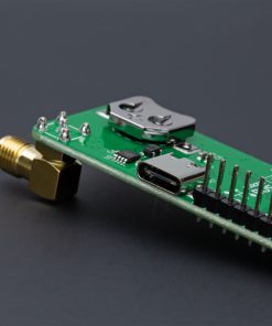
It is also equipped with a USB type C connector for a USB version 2.0 FS (Full Speed, 12 Mbit/s) compatible interface, available for communication as an alternative to the UART. With the help of the active USB voltage, the necessary power supply of the USB power block of the NEO-M8J is provided via the ADP1715 linear regulator. In the case of the primary supply failure, the module can use a backup supply voltage from a connected battery if you need the Click board™ to be a standalone device. Backup voltage supplies the real-time clock and battery-backed RAM and enables all relevant data to be saved in the backup RAM to allow a hot or warm start later.
In addition to these features, it also uses several GPIO pins. An active-low reset signal routed on the RST pin of the mikroBUS™ socket activates a hardware reset of the system, while the INT pin on the mikroBUS™ socket represents a standard interrupt feature providing a user with feedback information. It also has an additional interrupt marked as I1 and routed on the AN pin of the mikroBUS™ socket, used for module Wake-Up function, alongside a blue LED indicator marked as STATUS used for time pulse signal indication.
GNSS 10 Click possesses the SMA antenna connector with an impedance of 50Ω used to connect the appropriate active antenna that Mikroe has in its offer for improved range and received signal strength.
This Click board™ can be operated only with a 3.3V logic voltage level. The board must perform appropriate logic voltage level conversion before using MCUs with different logic levels. However, the Click board™ comes equipped with a library containing functions and an example code that can be used, as a reference, for further development.
Specifications
Type
GPS/GNSS
Applications
Can be used for industrial and automotive applications
On-board modules
NEO-M8J – high-performance GNSS module from u-blox
Key Features
Low power consumption, concurrent reception of up to 3 GNSS (GPS, Galileo, GLONASS, BeiDou), industry leading –167 dBm navigation sensitivity, security and integrity protection, supports all satellite augmentation systems, advanced jamming and spoofing detection, and more
Interface
I2C,SPI,UART,USB
Feature
No ClickID
Compatibility
mikroBUS™
Click board size
L (57.15 x 25.4 mm)
Input Voltage
3.3V
Pinout diagram
This table shows how the pinout on GNSS 10 Click corresponds to the pinout on the mikroBUS™ socket (the latter shown in the two middle columns).
Onboard settings and indicators
Label | Name | Default | Description |
---|---|---|---|
LD1 | PWR | – | Power LED Indicator |
LD2 | STATUS | – | Time Pulse LED Indicator |
JP1-JP5 | COMM SEL | Left | Communication Interface Selection SPI/UART: Left position SPI, Right position UART |
GNSS 10 Click electrical specifications
Description | Min | Typ | Max | Unit |
---|---|---|---|---|
Supply Voltage | – | 3.3 | – | V |
Operating Frequency Range | – | 1602 | – | MHz |
Tracking & Navigation Sensitivity | – | -164 | – | dBm |
Operating Temperature Range | -40 | +25 | +85 | °C |
Software Support
We provide a library for the GNSS 10 Click as well as a demo application (example), developed using MikroElektronika compilers. The demo can run on all the main MikroElektronika development boards.
Package can be downloaded/installed directly from NECTO Studio Package Manager(recommended way), downloaded from our LibStock™ or found on Mikroe github account.
Library Description
This library contains API for GNSS 10 Click driver.
Key functions
-
gnss10_reset_device
This function resets the device by toggling the RST pin. -
gnss10_generic_read
This function reads a desired number of data bytes from the module. -
gnss10_parse_gngga
This function parses the GNGGA data from the read response buffer.
Example Description
This example demonstrates the use of GNSS 10 Click by reading and displaying the GNSS coordinates.
void application_task ( void )
{
gnss10_process( &gnss10 );
if ( app_buf_len > ( sizeof ( GNSS10_RSP_GNGGA ) + GNSS10_GNGGA_ELEMENT_SIZE ) )
{
gnss10_parser_application( app_buf );
}
}
The full application code, and ready to use projects can be installed directly from NECTO Studio Package Manager(recommended way), downloaded from our LibStock™ or found on Mikroe github account.
Other Mikroe Libraries used in the example:
- MikroSDK.Board
- MikroSDK.Log
- Click.GNSS10
Additional notes and informations
Depending on the development board you are using, you may need USB UART click, USB UART 2 Click or RS232 Click to connect to your PC, for development systems with no UART to USB interface available on the board. UART terminal is available in all MikroElektronika compilers.
mikroSDK
This Click board™ is supported with mikroSDK – MikroElektronika Software Development Kit. To ensure proper operation of mikroSDK compliant Click board™ demo applications, mikroSDK should be downloaded from the LibStock and installed for the compiler you are using.
For more information about mikroSDK, visit the official page.