How does it work?
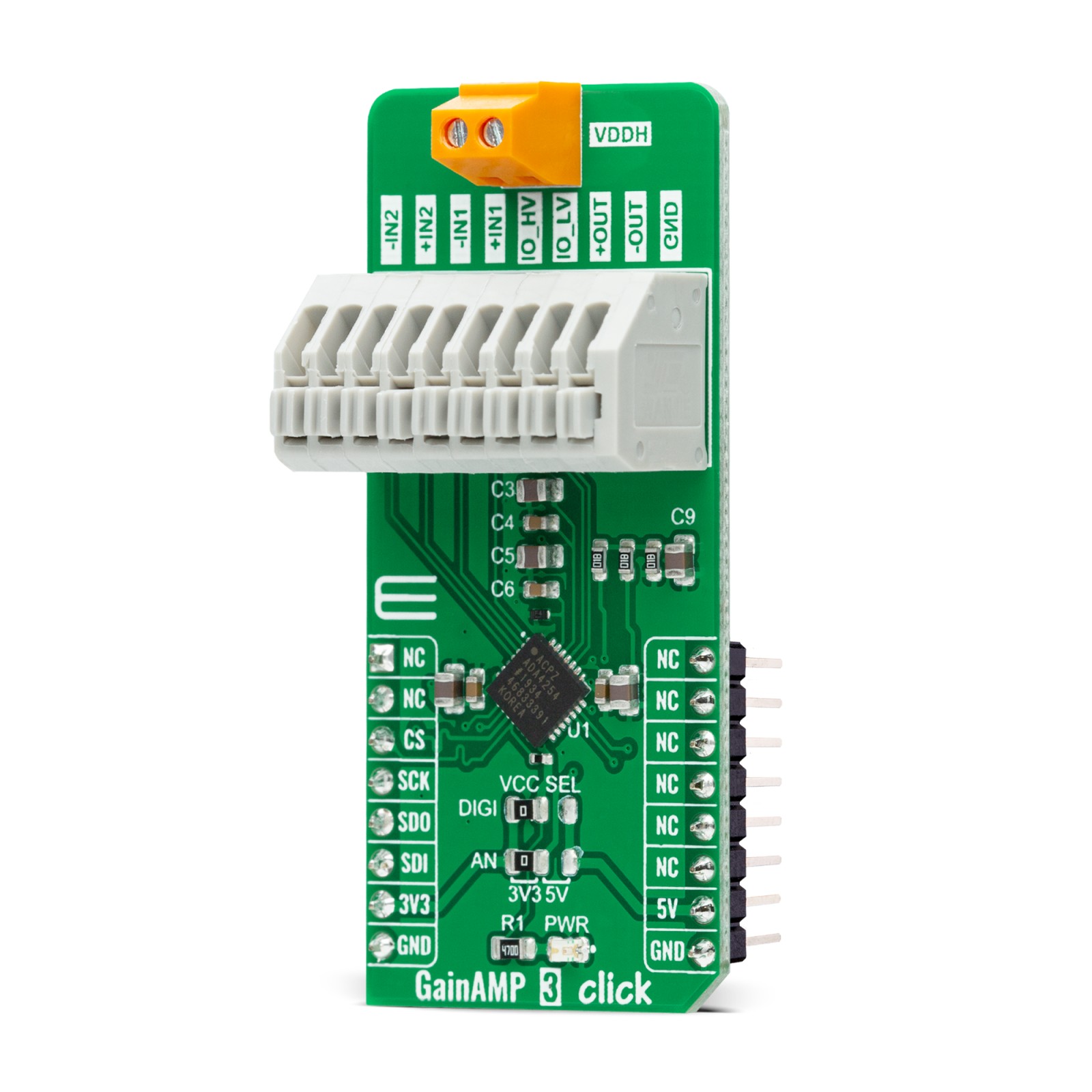
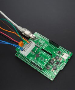
GainAMP 3 Click as its foundation uses the ADA4254, a zero drift, high voltage, programmable gain instrumentation amplifier (PGIA) designed for process control and industrial applications from Analog Devices. It accurately measures sensors, voltages, and currents with wide dynamic ranges and provides safety information about what is being measured. It features 12 binary weighted gains ranging from 1/16V/V to 128V/V and three scaling gain options of 1V/V, 1.25V/V, and 1.375V/V, resulting in 36 possible gain settings. Its zero-drift amplifier topology self-calibrates DC errors and low-frequency noise, achieving excellent DC precision over the entire specified temperature range, maximizing dynamic range, and significantly reducing calibration requirements in many applications.
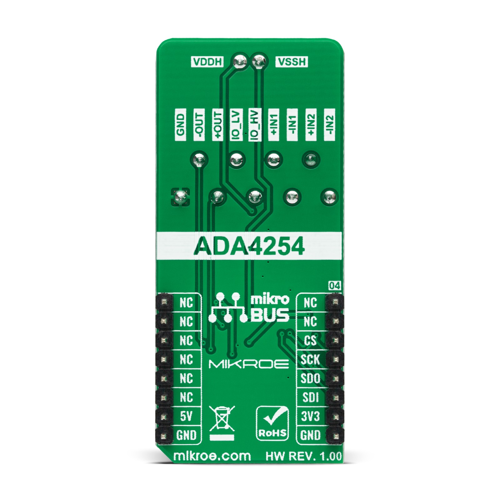
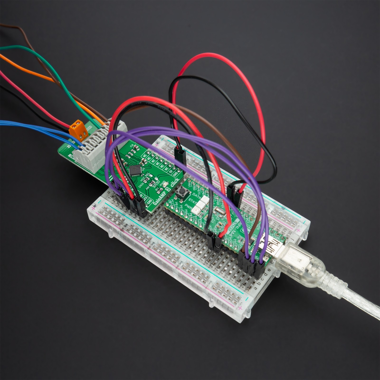
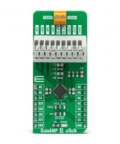
The ADA4254 communicates with MCU using the standard SPI serial interface with a maximum frequency of 5MHz, supporting the most common SPI mode, SPI Mode 0. It comes with a 4-channel input multiplexer providing ±60V protection to the high impedance inputs of the amplifier and an excitation current source output available to bias sensors such as resistance temperature detectors (RTDs). In addition to these channels located on the onboard 9-pole connector, the ADA4254 also has a differential output stage and output excitation current channels.
A differential output stage allows the device to be directly connected to high-precision ADCs. When making such a connection, it is recommended to use a low-pass filter before a connection to the ADCs to minimize noise and aliasing. A software configurable excitation current outputs can be used to excite external circuitry, such as resistive bridges or RTD sensors, and be programmed to a value from 100μA to 1.5mA in increments of 100μA.
This Click board™ can operate with both 3.3V and 5V logic voltage levels selected via the VCC SEL jumper. In addition to choosing the logic voltage level using jumper labeled as DIGI, it is also possible to select the supply voltage of the amplifier using the AN jumper by positioning SMD jumpers to an appropriate position. This way, it is allowed for both 3.3V and 5V capable MCUs to use the SPI communication lines properly. However, the Click board™ comes equipped with a library containing easy-to-use functions and an example code that can be used, as a reference, for further development.
Specifications
Type
Amplifier
Applications
Can be used for industrial systems and process control that demand precision, robustness, and low power, thanks to its low power consumption
On-board modules
ADA4254 – zero drift, high voltage, programmable gain instrumentation amplifier (PGIA) designed for process control and industrial applications from Analog Devices
Key Features
Low power consumption, optimized for ADC synchronization, 12 binary steps and 3 scaling gains, ±60V protection input mux, excellent DC precision, and more
Interface
SPI
Feature
No ClickID
Compatibility
mikroBUS™
Click board size
L (57.15 x 25.4 mm)
Input Voltage
3.3V or 5V,External
Pinout diagram
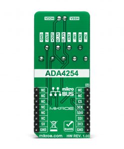
This table shows how the pinout on GainAMP 3 Click corresponds to the pinout on the mikroBUS™ socket (the latter shown in the two middle columns).
Onboard settings and indicators
Label | Name | Default | Description |
---|---|---|---|
LD1 | PWR | – | Power LED Indicator |
JP1 | VCC SEL-DIGI | Left | Logic Voltage Level Selection 3V3/5V: Left position 3V3, Right position 5V |
JP2 | VCC SEL-AN | Left | Amplifier Supply Voltage Level Selection 3V3/5V: Left position 3V3, Right position 5V |
GainAMP 3 Click electrical specifications
Description | Min | Typ | Max | Unit |
---|---|---|---|---|
Supply Voltage VCC | 3.3 | – | 5 | V |
External Supply Voltage VDDH − VSSH | 10(±5) | – | 56(±28) | V |
Gain Steps | 1/16 | – | 128 | V/V |
Operating Temperature Range | -40 | +25 | +125 | °C |
Software Support
We provide a library for the GainAMP 3 Click as well as a demo application (example), developed using MikroElektronika compilers. The demo can run on all the main MikroElektronika development boards.
Package can be downloaded/installed directly from NECTO Studio Package Manager(recommended way), downloaded from our LibStock™ or found on Mikroe github account.
Library Description
This library contains API for GainAMP 3 Click driver.
Key functions:
gainamp3_write_register
– This function writes a data byte to the selected register by using SPI serial interface.gainamp3_set_amplifier_gain
– This function sets the amplifier gain level.gainamp3_set_input_channel
– This function sets the input channel.
Examples description
This example demonstrates the use of GainAMP 3 Click board™.
void application_task ( void ) { for ( uint8_t cnt = GAINAMP3_GAIN_1_OVER_16; cnt <= GAINAMP3_GAIN_128; cnt++ ) { gainamp3_set_amplifier_gain ( &gainamp3, cnt ); log_printf( &logger, " Amplifier gain set to " ); float gain = ( 1 << cnt ) / 16.0; if ( gain < 1.0 ) { log_printf( &logger, "1/%urn", ( uint16_t ) ( 1.0 / gain ) ); } else { log_printf( &logger, "%urn", ( uint16_t ) gain ); } Delay_ms( 3000 ); } }
The full application code, and ready to use projects can be installed directly from NECTO Studio Package Manager(recommended way), downloaded from our LibStock™ or found on Mikroe github account.
Other Mikroe Libraries used in the example:
- MikroSDK.Board
- MikroSDK.Log
- Click.GainAMP3
Additional notes and informations
Depending on the development board you are using, you may need USB UART click, USB UART 2 click or RS232 click to connect to your PC, for development systems with no UART to USB interface available on the board. The terminal available in all MikroElektronika compilers, or any other terminal application of your choice, can be used to read the message.
mikroSDK
This Click board™ is supported with mikroSDK – MikroElektronika Software Development Kit. To ensure proper operation of mikroSDK compliant Click board™ demo applications, mikroSDK should be downloaded from the LibStock and installed for the compiler you are using.
For more information about mikroSDK, visit the official page.