How does it work?
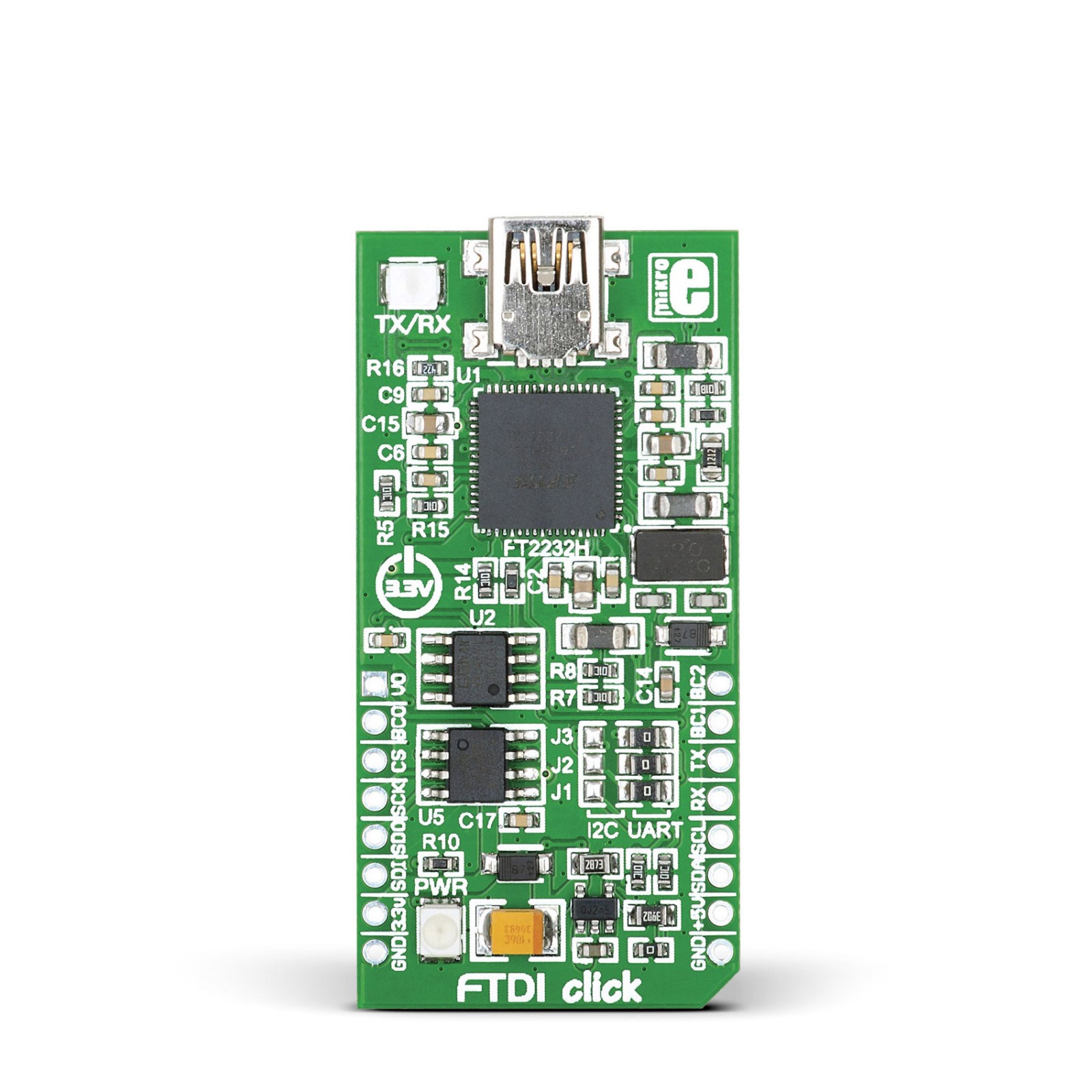
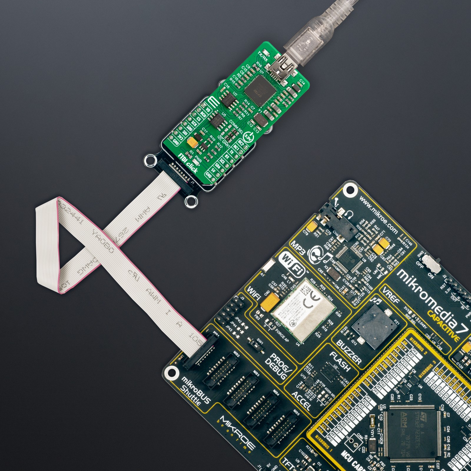
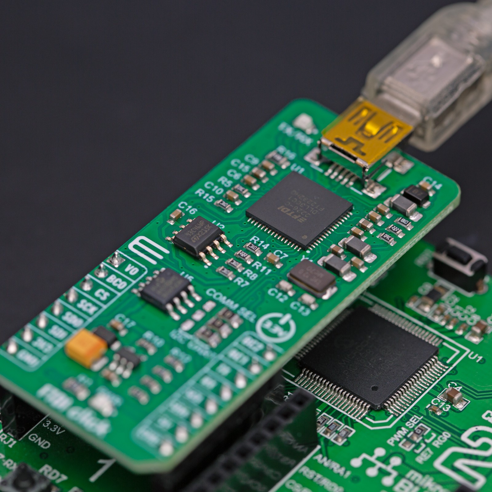
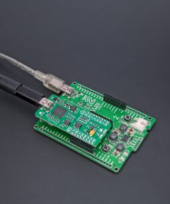
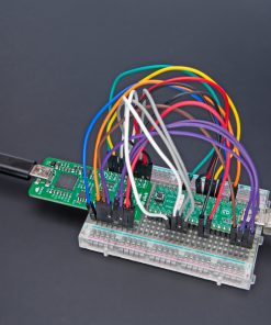
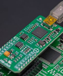
FTDI Click is based on the FT2232H, a 5th-generation high-speed USB to a serial interface converter from FTDI, capable of configuration in various industry standard serial or parallel interfaces. The entire USB protocol is handled on the chip, with no USB-specific firmware programming requirements, but requires USB device drivers for operation available free from the official FTDI page. It can work at high speed (480Mbps) and full speed (12Mbps), depending on the usage, alongside a dual Multi-Protocol Synchronous Serial Engine (MPSSE) used to simplify synchronous serial protocol between USB and available interfaces.
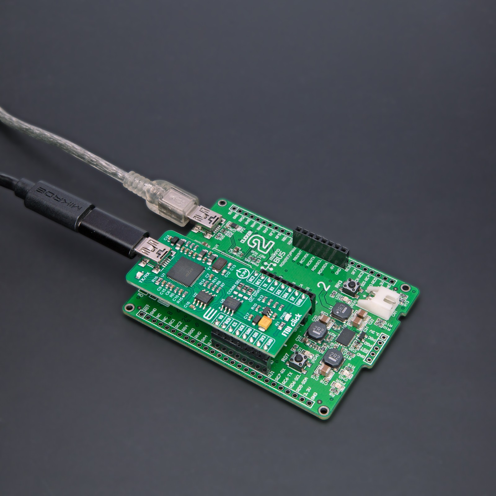
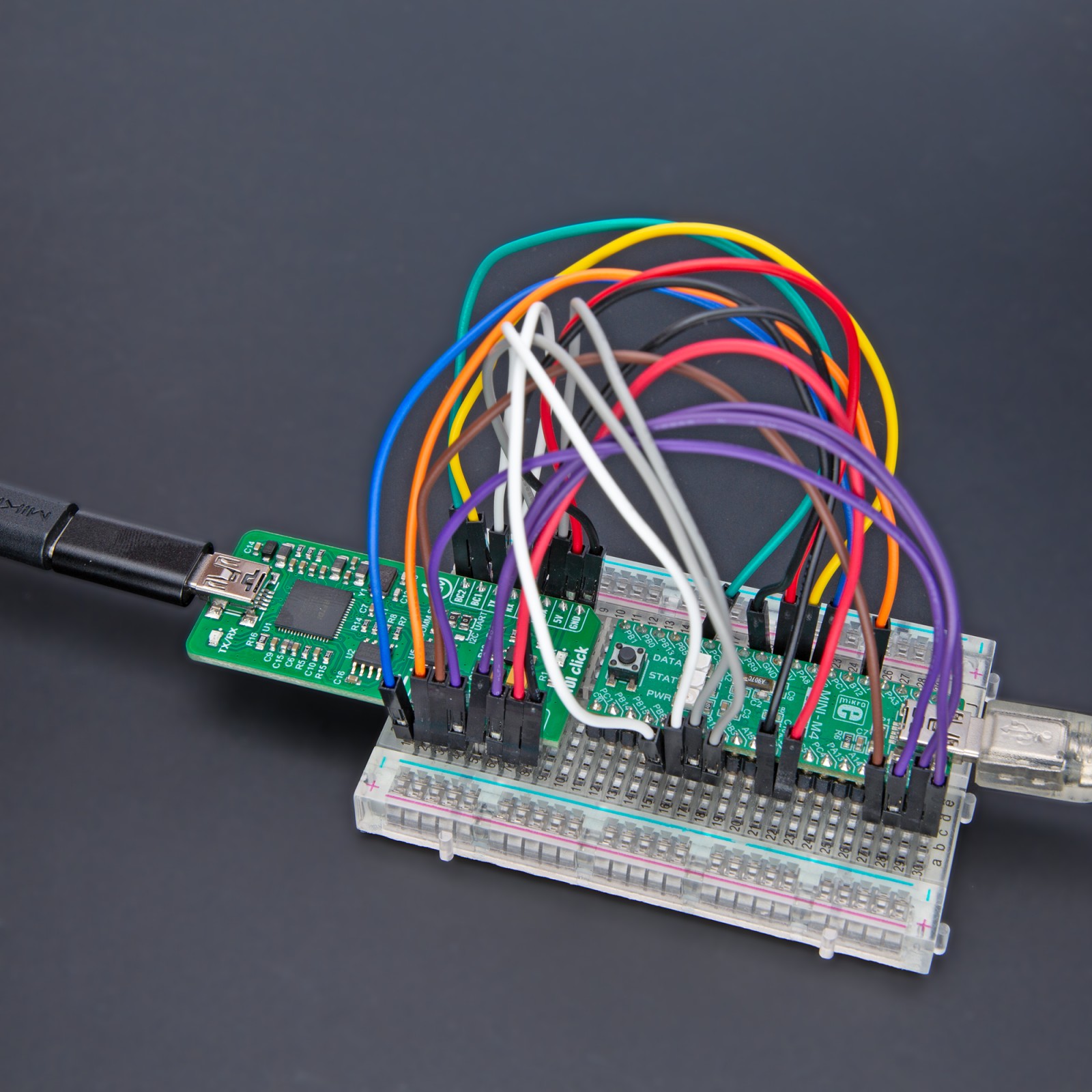
The FT2232H can communicate with the host MCU over the mikroBUS™ socket using one of the available interfaces (UART, I2C, SPI). The SPI interface can be used as is, while one of the other two has to be selected by the I2C UART jumper, with UART chosen as a default. Each interface is compatible with an LED indicator marked as TX/RX that signals data transmission. In addition to the communication pins, this board has some additional routed to the RST, PWM, and INT pins of the mikroBUS™ socket and marked as BC0, BC1, and BC2 used for configuration purposes for the MPSSE, or FIFO interface. For additional information on these pins, consult the attached FT2232H datasheet.
This Click board™ also features the CAT93C46, a 1K-bit serial EEPROM from Catalyst Semiconductor that can be accessed directly from the FT2232H. The FT2232H uses external EEPROM to configure operational configuration mode and USB description strings. The EEPROM also allows each of the FTDI’s channels to be independently configured. It customises various values and parameters, some of which are remoted Wake Up, power descriptor value, and more.
In addition, FTDI Click features the MCP4921, a 12-bit DAC from Microchip, that communicates with the host MCU over an SPI serial interface of the mikroBUS™ socket. Activated using an FTDI signal over a BD4, it can be used as a reference for external peripherals with a value from the VO pin routed to the AN pin of the mikroBUS™ socket.
This Click board™ can be operated only with a 3.3V logic voltage level. Considering that the board can be powered via USB and used as a standalone device, using an additional LDO, the AP7331, in this way, the existence of the voltage of both mikroBUS™ power lines is ensured. The board must complete the proper logic voltage level conversion before use with MCUs with different logic levels. However, the Click board™ comes equipped with a library from FTDI, containing functions and an example code that can be used, as a reference, for further development.
Specifications
Type
USB
Applications
Can be used for various industry-standard applications suitable for development purposes by adding USB to a target design
On-board modules
FT2232H – USB 2.0 to serial interface converter from FTDI
CAT93C46 – a 1Kbit serial EEPROM from Catalyst Semiconductor
Key Features
High speed, MPSSE to simplify synchronous serial protocol, FIFO interface, transmit/receive indicator, EEPROM for operational configuration, communication selection, DAC for external peripherals, and more
Interface
I2C,SPI,UART,USB
Feature
No ClickID
Compatibility
mikroBUS™
Click board size
L (57.15 x 25.4 mm)
Input Voltage
3.3V,5V
Pinout diagram
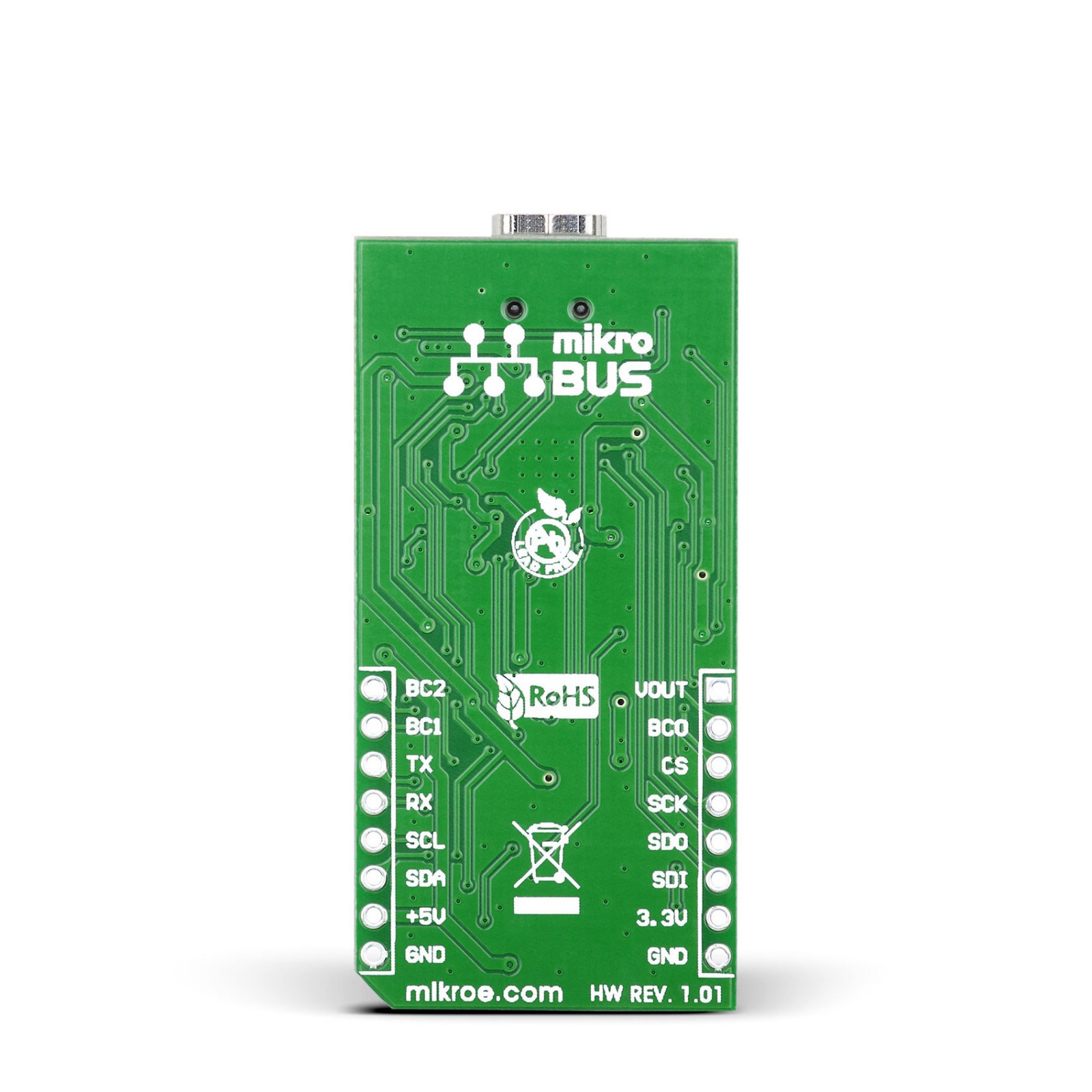
This table shows how the pinout on FTDI Click corresponds to the pinout on the mikroBUS™ socket (the latter shown in the two middle columns).
Onboard settings and indicators
Label | Name | Default | Description |
---|---|---|---|
LD1 | PWR | – | Power LED Indicator |
LD2 | TX/RX | – | Transmit/Receive LED Indicator |
J1-J3 | COMM SEL | Right | Communication Interface Selection: Left position I2C, Right position UART |
FTDI Click electrical specifications
Description | Min | Typ | Max | Unit |
---|---|---|---|---|
Supply Voltage | 3.3 | – | 5 | V |
USB Data Rate | – | – | 480 | Mbps |