How does it work?
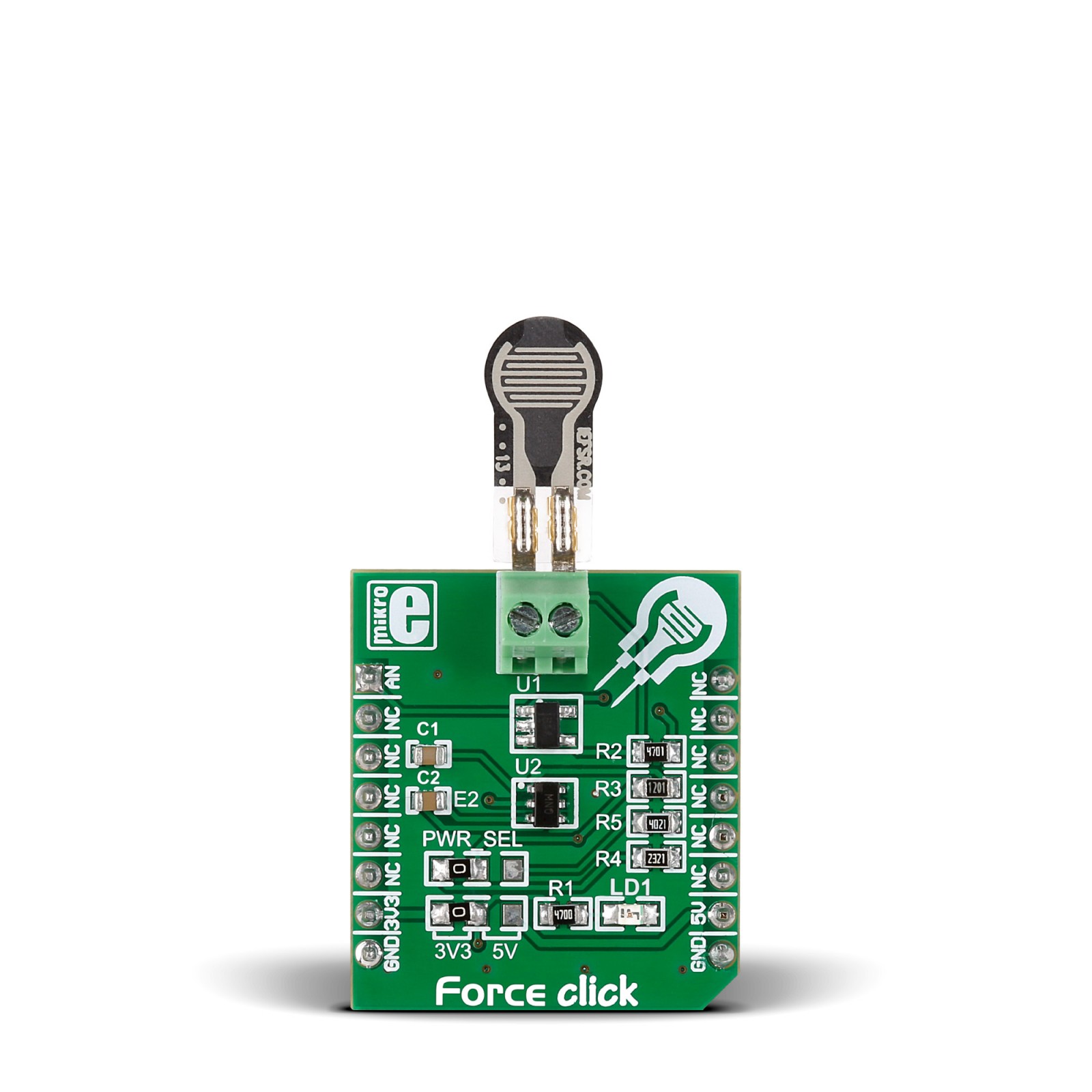
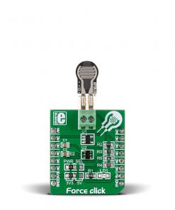
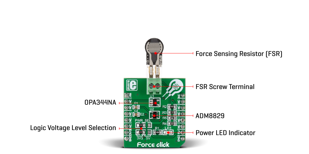
Force Click is based on the circuitry that allows the implementation of Force Sensing Resistors from Interlink Electronics. The Force Sensing Resistor is a thin sensor made of two membranes separated by a spacer around the edges. When pressed, the gap between the two membranes gets closed. This shorts the two membranes together with a resistance proportional to the applied force. This force sensitivity is optimized for human-machine interface devices, including automotive electronics, medical systems, industrial controls, and robotics. The FSR is a robust sensor with up to 10M of actuation and features a low device rise time of under 3 microseconds, as well as continuous analog force resolution.
Force Click sends analog values to the host MCU over the AN pin of the mikroBUS™ socket by using an OPA344, a low-power, single supply, rail-to-rail operational amplifier from Texas Instruments. This unity-gain stable OPAMP is ideal for driving sampling analog to digital converters. Rail-to-rail input and output swing significantly increase dynamic range, especially in low-power supply applications. The input to this OPA344NA is driven directly from the screw terminal and the force-sensing resistor.
An ADM8829, a switched-capacitor voltage inverter with shutdown from Analog Devices, feeds the other side of the screw terminal and the force-sensing resistor. This charge-pump voltage inverter generates a negative power supply from a positive input. The voltage conversion task is achieved using a switched capacitor technique using two external charge storage capacitors. An on-chip oscillator and switching network transfers charge between the charge storage capacitors.
This Click board™ can operate with either 3.3V or 5V logic voltage levels selected via the PWR SEL jumper. This way, both 3.3V and 5V capable MCUs can use the communication lines properly. However, the Click board™ comes equipped with a library containing easy-to-use functions and an example code that can be used, as a reference, for further development.
Specifications
Type
Force
Applications
Can be used for development of applications with simple to implement force (pressure) measurement (when squeezed), and is not recommended if high accuracy is required
On-board modules
OPA344 – single supply rail-to-rail operational amplifier from Texas Instruments
Key Features
Screw terminal for Force Sensing Resistor, one single zone force sensing resistor (FSR® 400 Short) included with the Click board™, analog output, and more
Interface
Analog
Feature
No ClickID
Compatibility
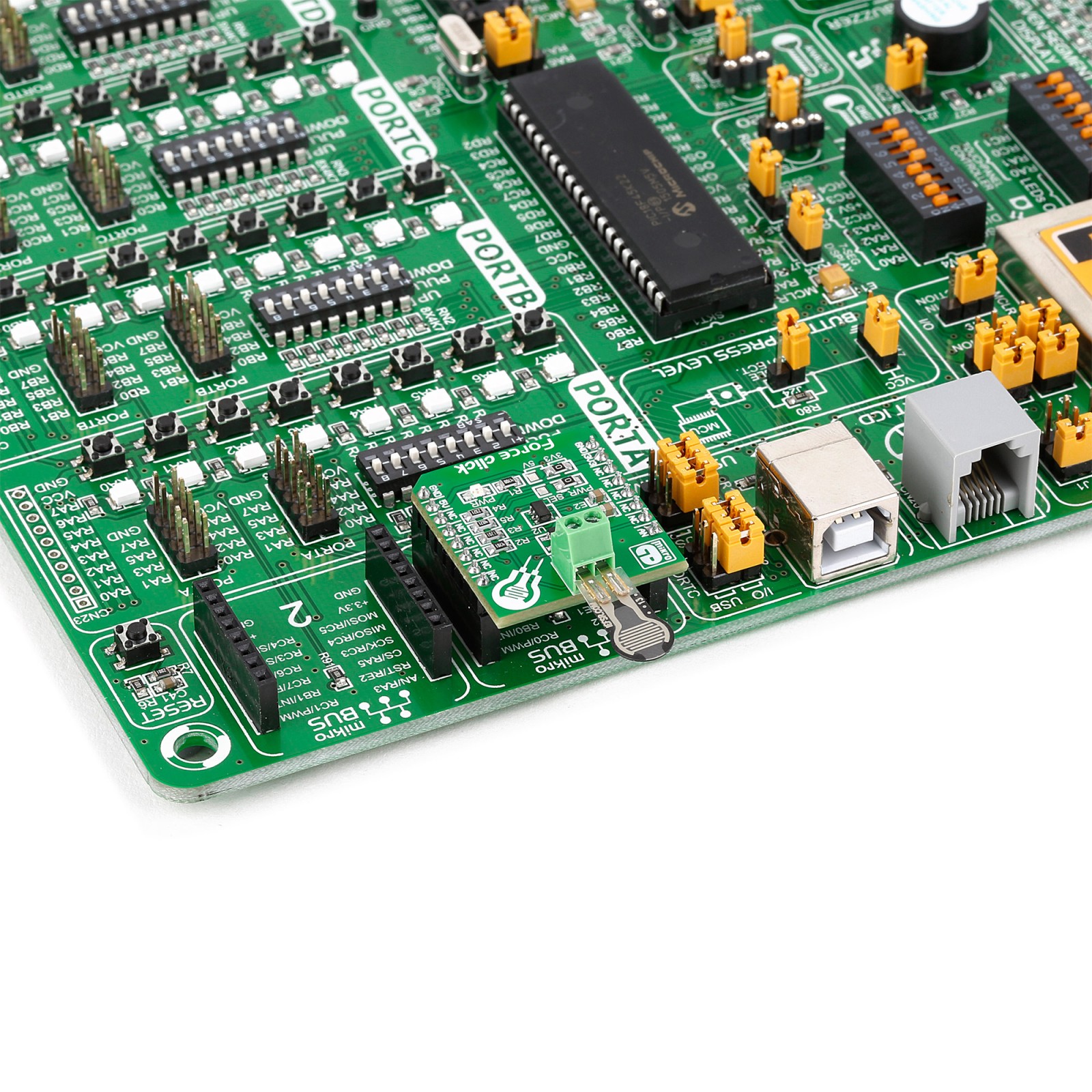
mikroBUS™
Click board size
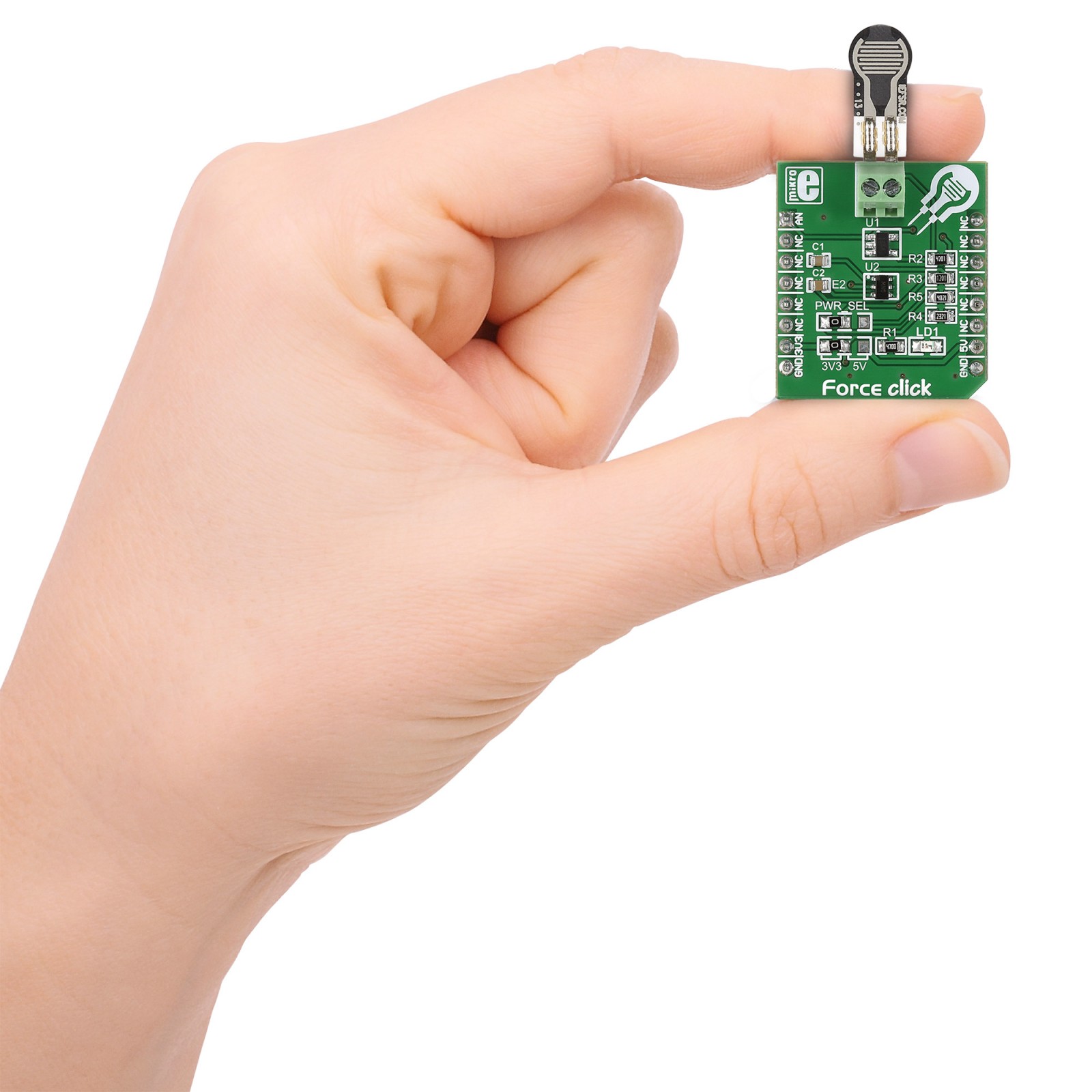
S (28.6 x 25.4 mm)
Input Voltage
3.3V or 5V
Pinout diagram
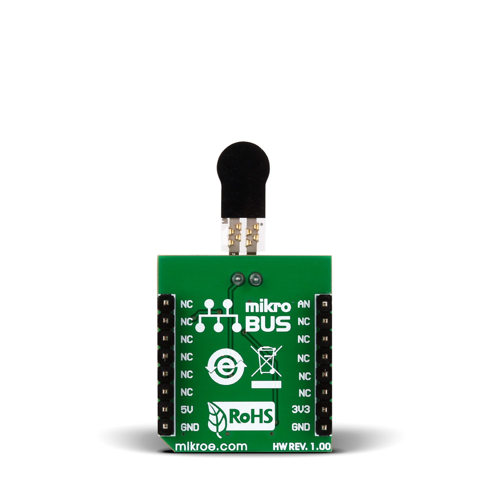
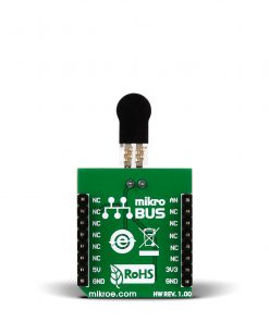
This table shows how the pinout on Force Click corresponds to the pinout on the mikroBUS™ socket (the latter shown in the two middle columns).
Onboard settings and indicators
Label | Name | Default | Description |
---|---|---|---|
LD1 | PWR | – | Power LED Indicator |
JP1 | PWR SEL | Left | Logic Level Voltage Selection 3V3/5V: Left position 3V3, Right position 5V |
Force Click electrical specifications
Description | Min | Typ | Max | Unit |
---|---|---|---|---|
Supply Voltage | 3.3 | – | 5 | V |
Force Range | 0.2 | – | 20 | N |
Software Support
We provide a library for the Force Click as well as a demo application (example), developed using MIKROE compilers. The demo can run on all the main MIKROE development boards.
Package can be downloaded/installed directly from NECTO Studio Package Manager (recommended), downloaded from our LibStock™ or found on Mikroe github account.
Library Description
This library contains API for Force Click driver.
Key functions
-
This function reads ADC data.
-
This function calculates resistance data based on the ADC input.
-
This function calculates the correction factor based on temperature and humidity data.
Example Description
This example showcases how to initialize and configure the logger and click modules and read and display ADC voltage data read from the analog pin.
void application_task ( )
{
force_data_t tmp;
// Task implementation.
tmp = force_generic_read ( &force );
log_printf( &logger, " * ADC value : %d rn", tmp );
log_printf( &logger, "--------------------- rn" );
Delay_ms( 1000 );
}
The full application code, and ready to use projects can be installed directly from NECTO Studio Package Manager (recommended), downloaded from our LibStock™ or found on Mikroe github account.
Other Mikroe Libraries used in the example:
- MikroSDK.Board
- MikroSDK.Log
- Click.Force
Additional notes and informations
Depending on the development board you are using, you may need USB UART click, USB UART 2 Click or RS232 Click to connect to your PC, for development systems with no UART to USB interface available on the board. UART terminal is available in all MIKROE compilers.
mikroSDK
This Click board™ is supported with mikroSDK – MIKROE Software Development Kit, that needs to be downloaded from the LibStock and installed for the compiler you are using to ensure proper operation of mikroSDK compliant Click board™ demo applications.
For more information about mikroSDK, visit the official page.