How does it work?
The FSS1500NGT force sensor incorporates Honeywell sensing technology that uses a specialized piezoresistive micromachined silicon sensing element. The low power, unamplified, uncompensated Wheatstone bridge circuit design provides inherently stable mV output over the force range. The sensor package design incorporates patented modular construction. The use of innovative elastomeric technology and engineered molded plastics results in load excitation capacities up to 60 N (range dependent). The stainless steel ball provides excellent mechanical stability, and is suitable for a variety of potential medical and commercial applications.
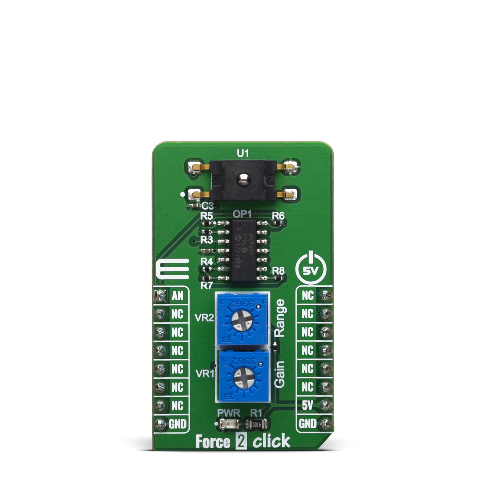
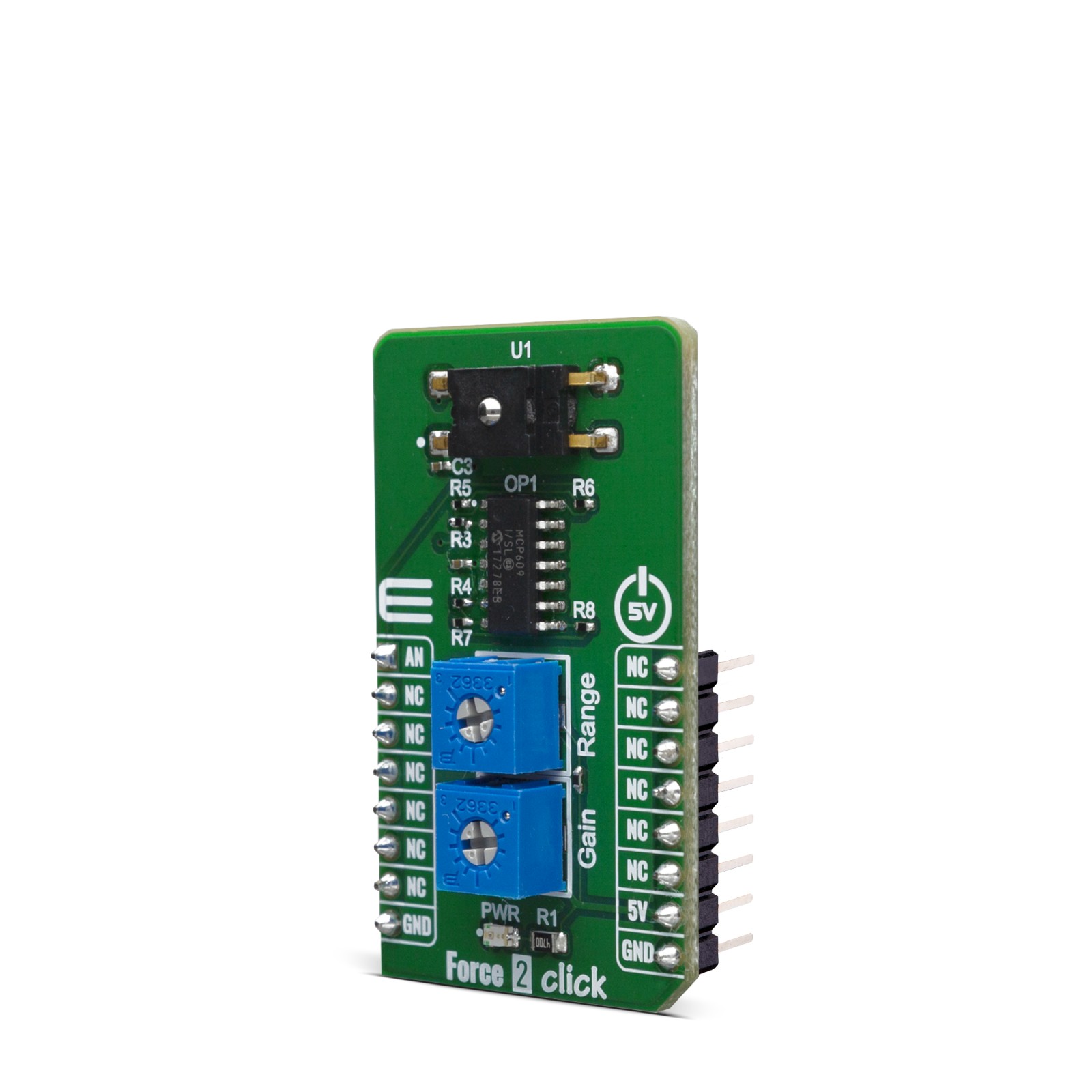
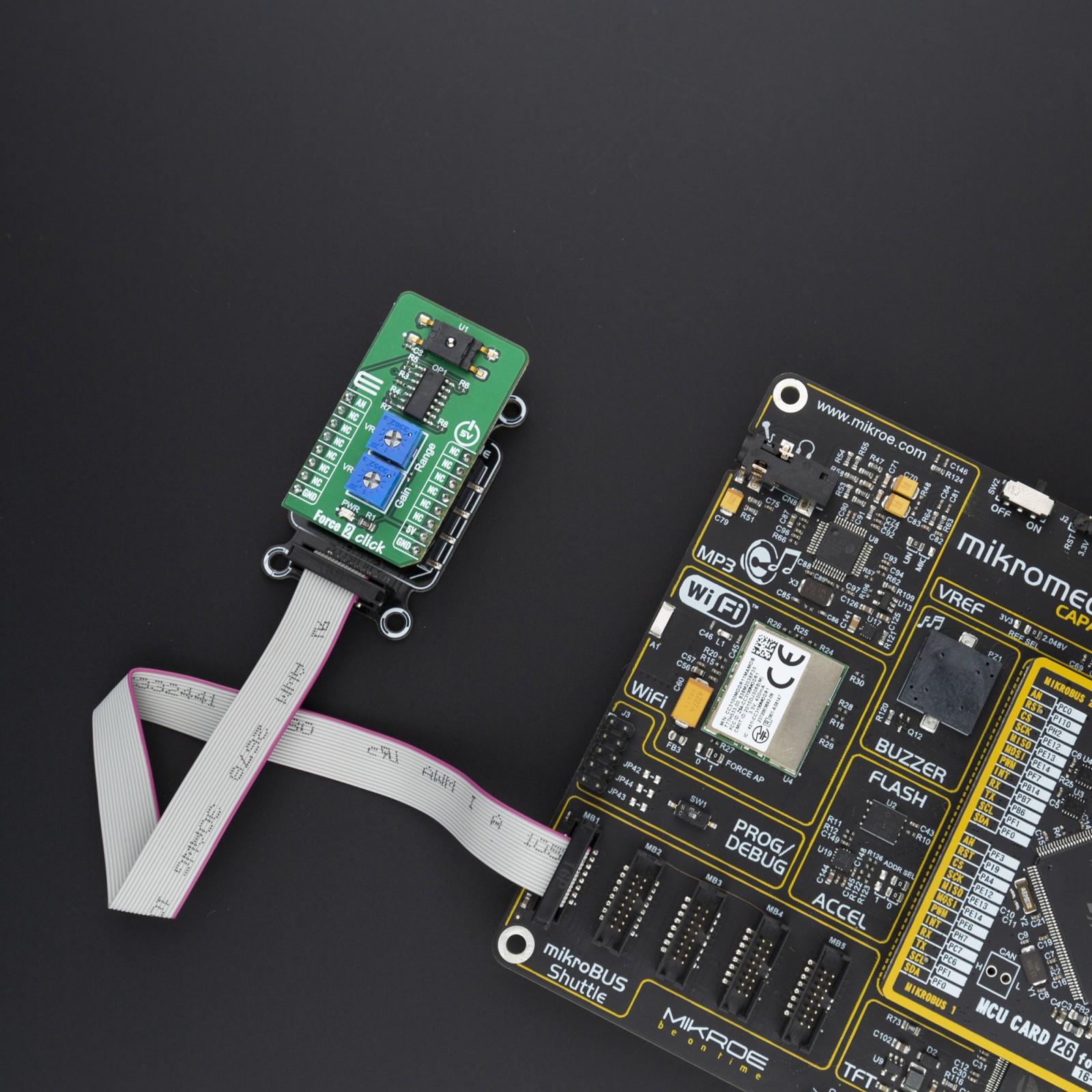
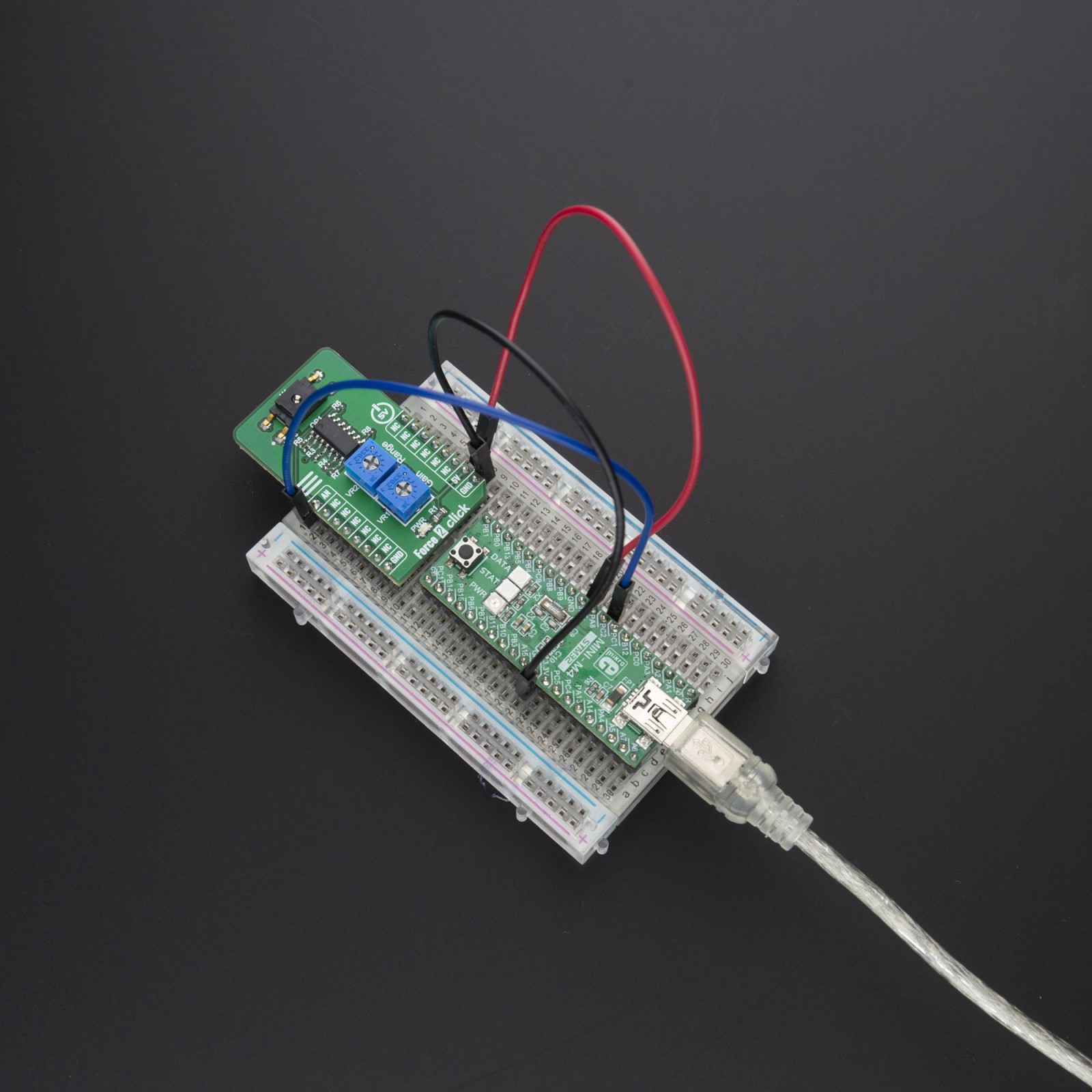
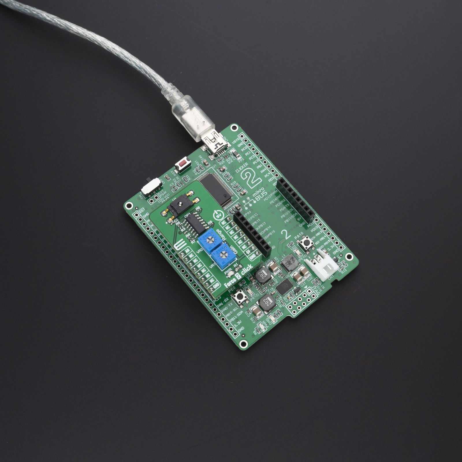
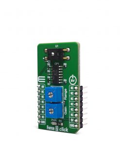
Force 2 Click also contains all the needed circuitry, required to get precise measurements from the sensor. It includes four operational amplifiers in total, forming one differential amplifier, with voltage adder, which can be used to set the measurement range. Gain setting is also available, in order to enable user to easily set this click board according to various needs. Range and gain are both set using the onboard multi-turn trimmers VR1 and VR2. That way, it is ensured that the precise setting can easily be done. The output of the differential amplifier is connected to the analog pin AN of mikroBUS™.
Force sensors operate on the principle that the resistance of silicon-implanted piezoresistors will change when the resistors flex under applied force. The sensor concentrates force from the applications, through the stainless steel ball, directly to the silicon-sensing element. The amount of resistance changes in proportion to the amount of force being applied. This change in circuit resistance results in a corresponding mV output level change. Low voltage supply allows for use in many battery powered applications.
Force 2 Click have FSS1500NGT force sensor on it and the force sensing range is 0-15N with overforce (the maximum force which may safely be applied to the product for it to remain in specification once force is returned to the operating force range) up to 45N.
The power supply is 5V and this allows only 5V MCUs to be interfaced with the Click boards™ directly.
Specifications
Type
Force
Applications
FSS1500NGT sensor is used in medical and industrial purposes, like infusionand ambulatory non-invasive pumps, kidney dialysis machines, load and compression sensing, variable tension control, robotic end-effector, etc.
On-board modules
FSS015NGT Honeywell’s FSS-SMT Series force sensor
Key Features
FSS015NGT force sensor on it and the force sensing range is 0-15N with overforce up to 45N
Interface
Analog
Feature
No ClickID
Compatibility
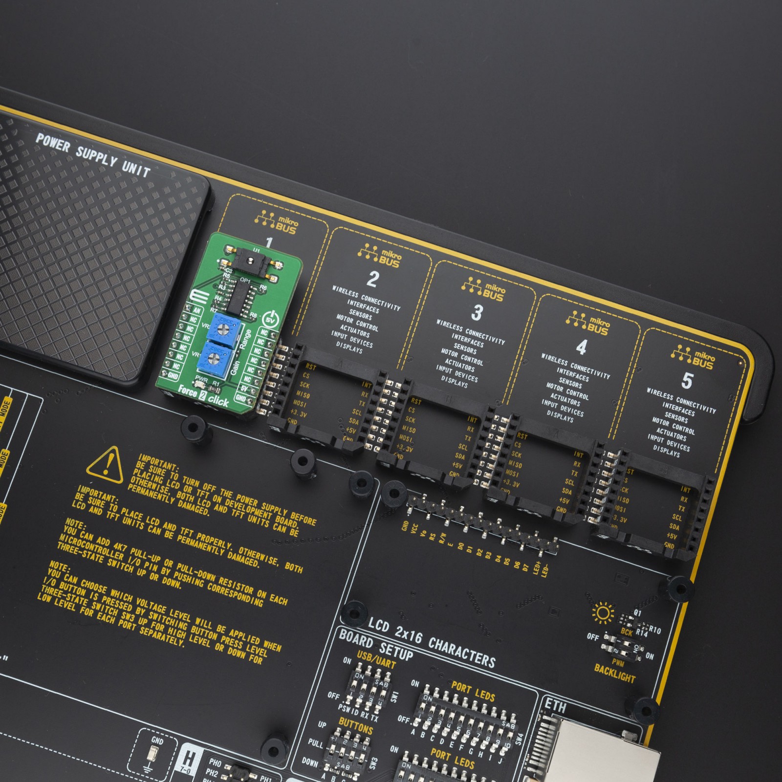
mikroBUS™
Click board size
S (28.6 x 25.4 mm)
Input Voltage
5V
Pinout diagram
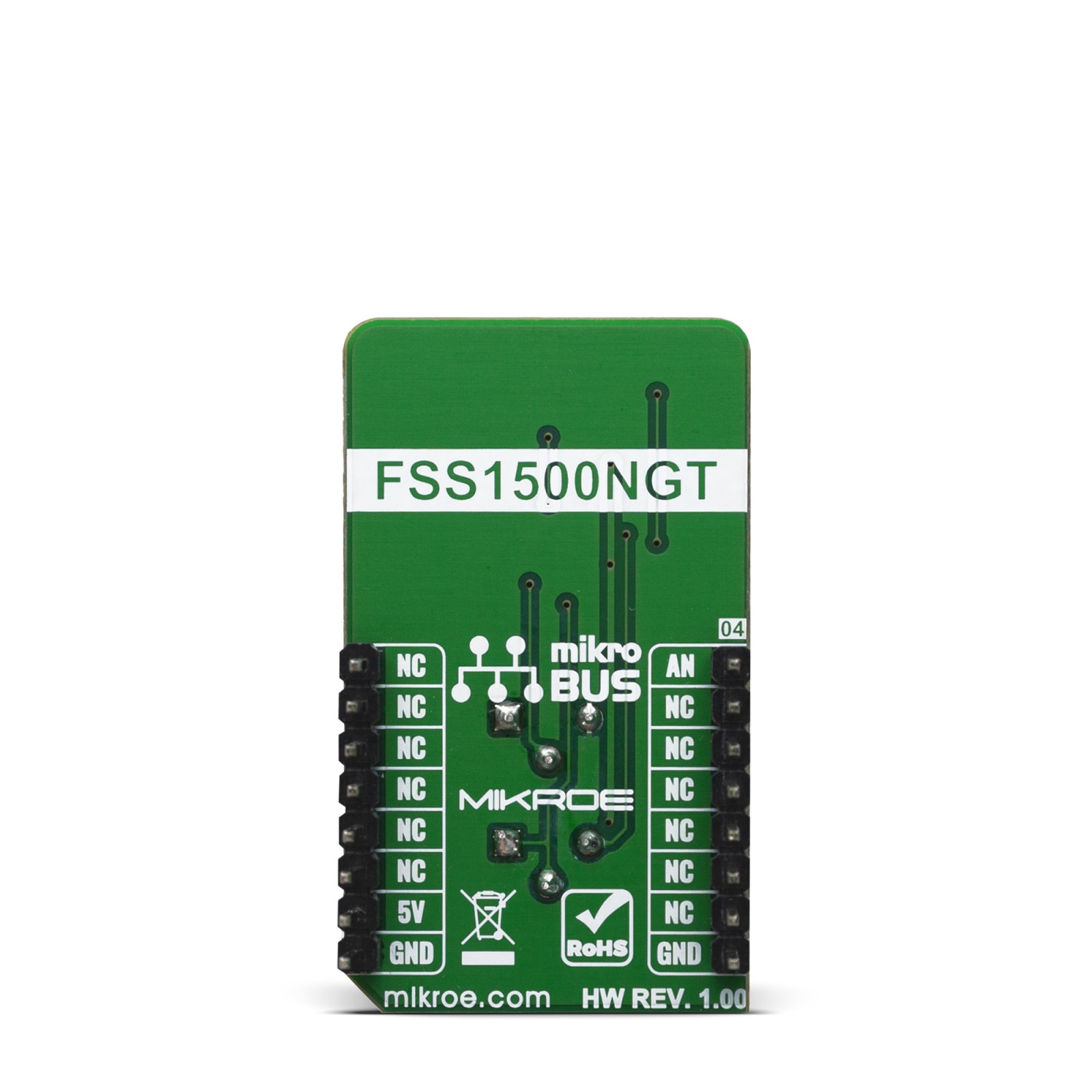
This table shows how the pinout on Force 2 Click corresponds to the pinout on the mikroBUS™ socket (the latter shown in the two middle columns).
Onboard settings and indicators
Label | Name | Default | Description |
---|---|---|---|
LD1 | PWR | – | Power LED Indicator |
VR1 | Gain | – | Gain adustment potentiometer |
VR2 | Range | – | Range adustment potentiometer |
Software Support
We provide a library for the Force 2 Click on our LibStock page, as well as a demo application (example), developed using MikroElektronika compilers. The demo can run on all the main MikroElektronika development boards.
Library Description
The library covers all the necessary functions to control Force 2 Click board.
Key functions:
force2_adc_set_in_channel( );
– Function sets input channel.force2_adc_init( );
– Function initializes ADC.force2_adc_read( );
– Function reads ADC values.
Examples description
The application is composed of three sections :
- System Initialization – Initializes GPIO and LOG structures, set AN pin as input.
- Application Initialization – Initalizes ADC driver, sets ADC channel and makes an initial log.
- Application Task – (code snippet) This is an example that shows the capabilities of the Force 2 Click by taking measurements from the device and displaying it via USART terminal.
void application_task ( ) { adc_val = force2_adc_read( ); disp_val = force2_val_conv( adc_val, 4095, 15, 0 ); ByteToStr( disp_val, log_txt ); Ltrim( log_txt ); mikrobus_logWrite( "Force: ", _LOG_TEXT ); mikrobus_logWrite( log_txt, _LOG_TEXT ); mikrobus_logWrite( "N", _LOG_LINE ); mikrobus_logWrite( "-------------------", _LOG_LINE ); Delay_ms( 500 ); }
force2_val_conv ( uint32_t x, uint32_t in_max, uint32_t out_min, uint32_t out_max )
– re-maps ADC value to force value in newton.force2_adc_set_in_channel( );
– Function sets input channel.force2_adc_init( );
– Function initializes ADC.force2_adc_read( );
– Function reads ADC values.
The full application code, and ready to use projects can be found on our LibStock page.
Other mikroE Libraries used in the example:
- ADC
- Conversions
- UART
Additional notes and informations
Depending on the development board you are using, you may need USB UART click, USB UART 2 click or RS232 click to connect to your PC, for development systems with no UART to USB interface available on the board. The terminal available in all MikroElektronika compilers, or any other terminal application of your choice, can be used to read the message.
mikroSDK
This Click board™ is supported with mikroSDK – MikroElektronika Software Development Kit. To ensure proper operation of mikroSDK compliant Click board™ demo applications, mikroSDK should be downloaded from the LibStock and installed for the compiler you are using.
For more information about mikroSDK, visit the official page.