How does it work?
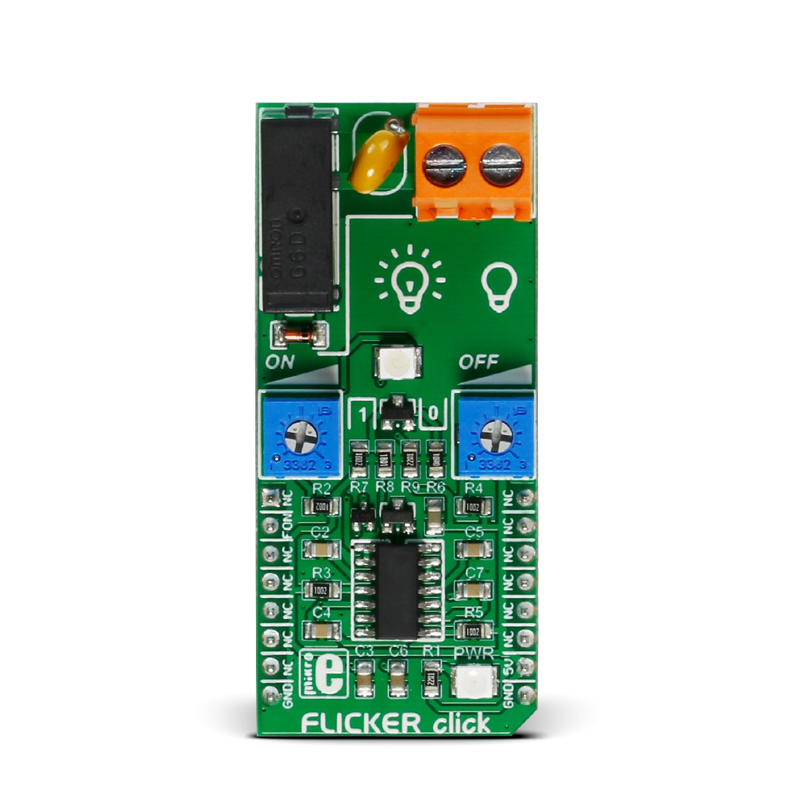
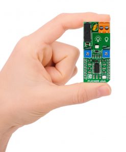
Flicker Click is based on the G6D-ASI, a power PCB relay from OMRON. It has a long service life with up to 300.000 operations at maximum rated loads. Its contact resistance is 100mΩ, with 5ms of release time, and it is designed to withstand 500VDC. Its coil is powered by 5V from the mikroBUS™ socket. The load can be connected to the relay over the onboard screw terminal and isolated from the board. Remember not to touch the board while the external power supply is on; the Flicker Click has exposed pins/pads.
Thanks to the onboard NE556, a dual precision timer from Texas Instruments, and two onboard 500K potentiometers, you can easily set the on/off periods. You will need a fine screwdriver to set the desired position of the potentiometers. A stopwatch can measure the ON/OFF periods if you need precise time. This way, you can set different or the same periods for both on and off states. The onboard LED stands for the visual presentation of the status of the relay. The Flicker Click uses a FON pin of the mikroBUS™ socket to communicate with the host MCU. Over this pin, you can turn the NE556 ON and OFF.
This Click board™ can only be operated with a 5V logic voltage level. The board must perform appropriate logic voltage level conversion before using MCUs with different logic levels. However, the Click board™ comes equipped with a library containing functions and an example code that can be used as a reference for further development.
Specifications
Type
Relay
Applications
Can be used for the development of applications where there is a need to turn on and off devices at specific time intervals, such as blinking LED commercials, alarm system lights, or any other signaling lights
On-board modules
G6D-ASI – power PCB relay from OMRON
NE556 – dual precision timer from Texas Instruments
Key Features
Setting the on and off periods independently via two potentiometers, maximum load up to 5A, 250VAC/30VDC, minimum permissible load 10mA at 5VDC, contact resistance 100mΩ maximum, and more
Interface
GPIO
Feature
No ClickID
Compatibility
mikroBUS™
Click board size
L (57.15 x 25.4 mm)
Input Voltage
5V
Pinout diagram
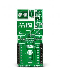
This table shows how the pinout on FLICKER Click corresponds to the pinout on the mikroBUS™ socket (the latter shown in the two middle columns).
Onboard settings and indicators
Label | Name | Default | Description |
---|---|---|---|
LD1 | PWR | – | Power LED Indicator |
LD2 | – | – | Relay Status LED Indicator |
P1 | ON | – | ON Period Setting Potentiometer |
P2 | OFF | – | OFF Period Setting Potentiometer |
FLICKER Click electrical specifications
Description | Min | Typ | Max | Unit |
---|---|---|---|---|
Supply Voltage | – | 5 | – | V |
Operating AC Voltage | – | – | 250 | V |
Operating DC Voltage | – | – | 30 | V |
Operating Current | – | – | 5 | A |
Software Support
We provide a library for the Flicker Click as well as a demo application (example), developed using MIKROE compilers. The demo can run on all the main MIKROE development boards.
Package can be downloaded/installed directly from NECTO Studio Package Manager (recommended), downloaded from our LibStock™ or found on Mikroe github account.
Library Description
This library contains API for Flicker Click driver.
Key functions
- Flicker engage function.
Example Description
This application simple solution if you need to turn a device on and off at specific time intervals.
void application_task ( void )
{
log_printf( &logger, " *Flicker on!* r/n/" );
flicker_engage( &flicker );
}
The full application code, and ready to use projects can be installed directly from NECTO Studio Package Manager (recommended), downloaded from our LibStock™ or found on Mikroe github account.
Other Mikroe Libraries used in the example:
- MikroSDK.Board
- MikroSDK.Log
- Click.Flicker
Additional notes and informations
Depending on the development board you are using, you may need USB UART click, USB UART 2 Click or RS232 Click to connect to your PC, for development systems with no UART to USB interface available on the board. UART terminal is available in all MIKROE compilers.
mikroSDK
This Click board™ is supported with mikroSDK – MIKROE Software Development Kit. To ensure proper operation of mikroSDK compliant Click board™ demo applications, mikroSDK should be downloaded from the LibStock and installed for the compiler you are using.
For more information about mikroSDK, visit the official page.