How does it work?
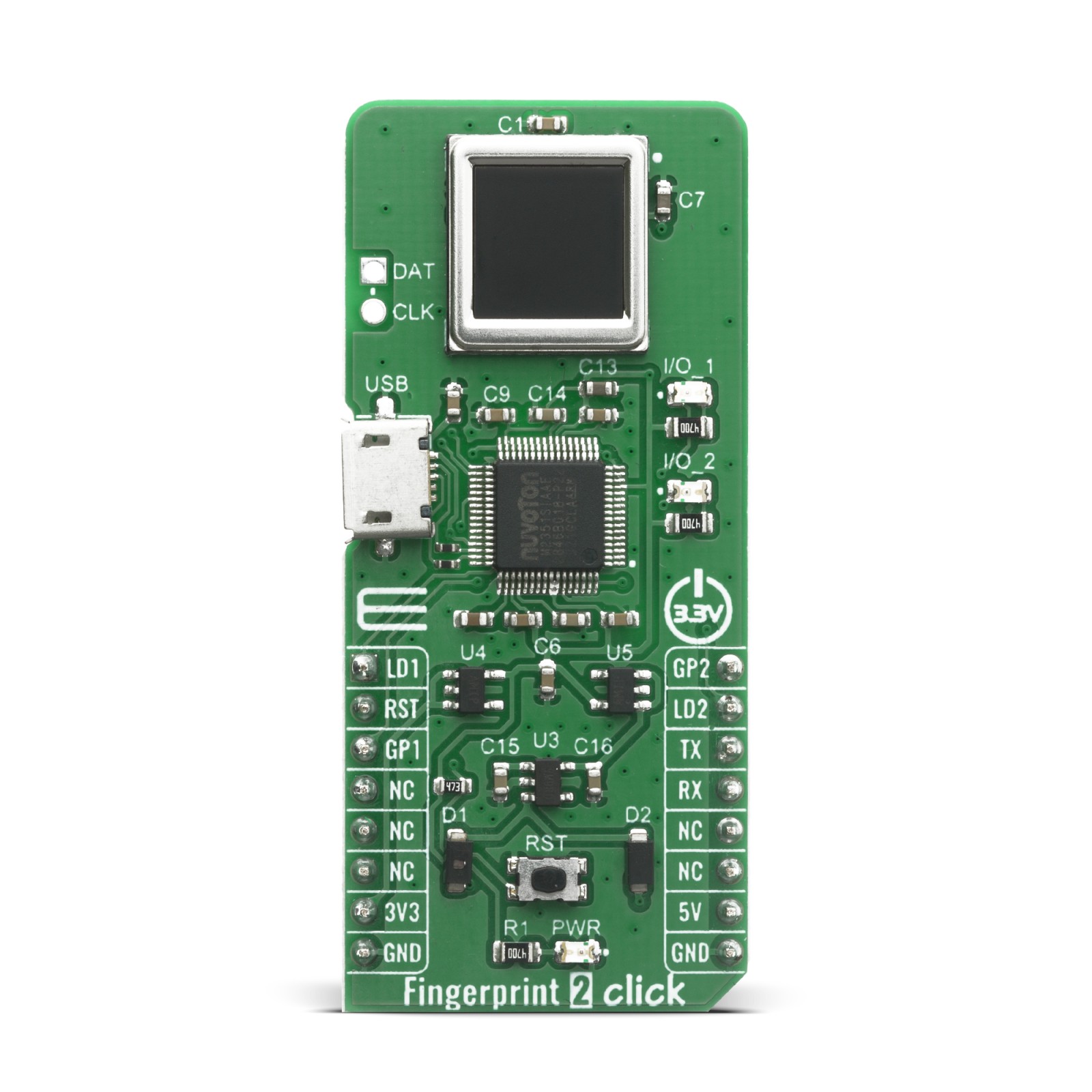
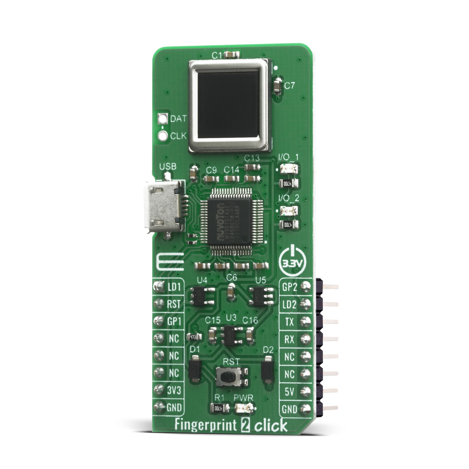
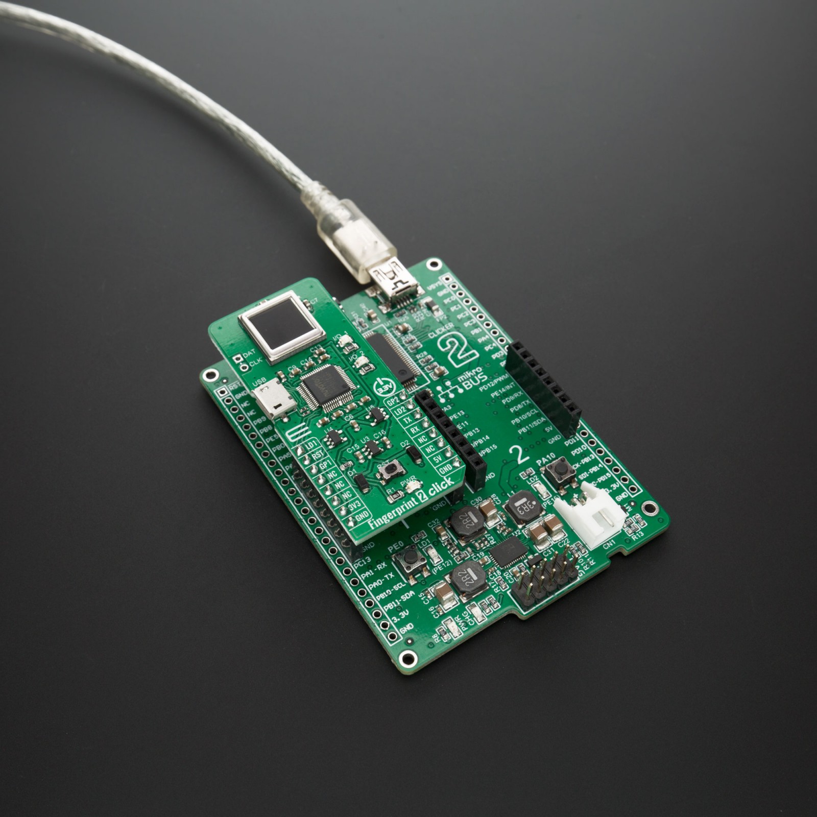
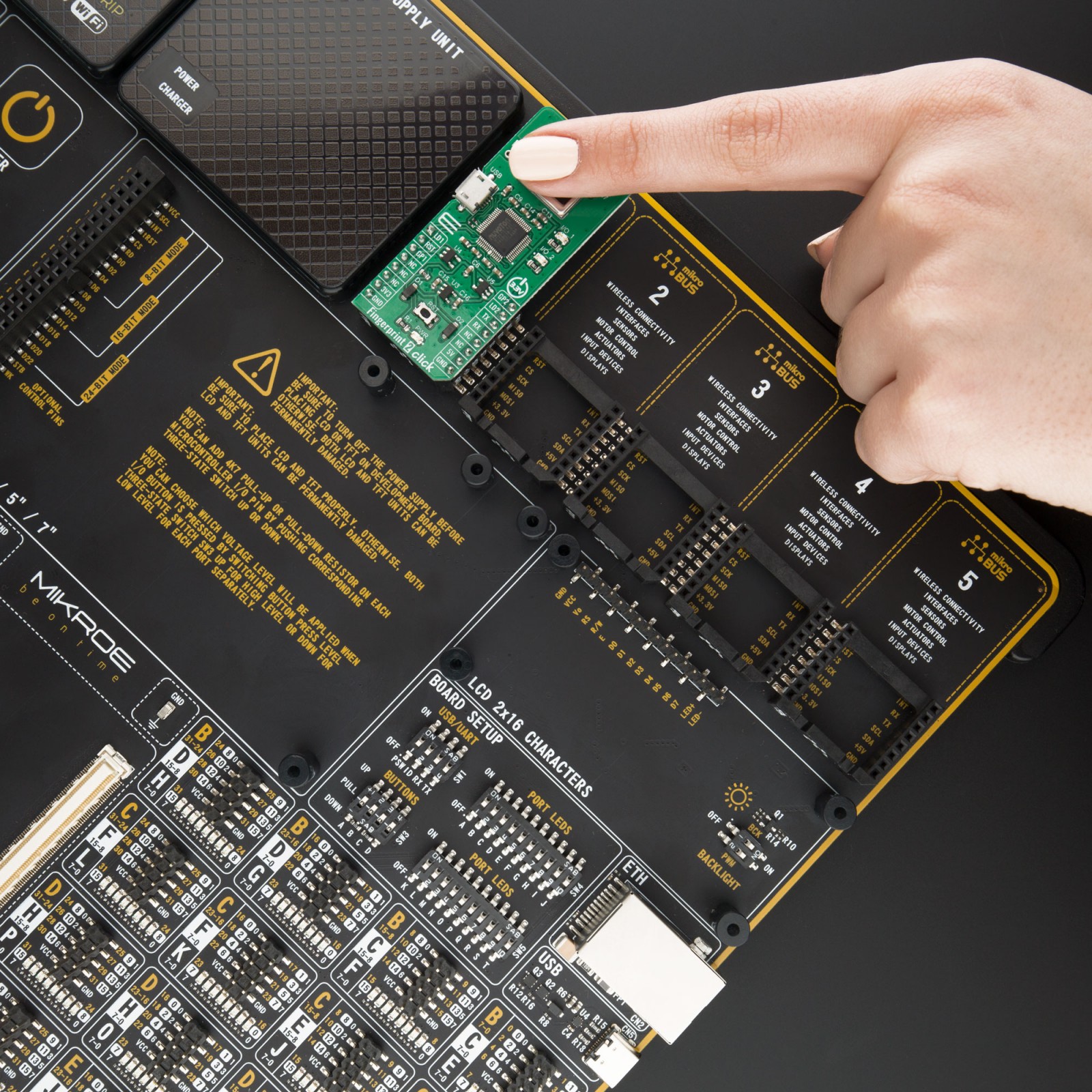
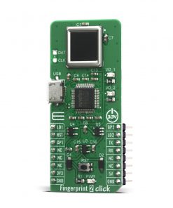
This click boars features an A-172-MRQ, a 2D capacitive fingerprint sensor with active scanning area of 8.8 x 8×8 mm and resolution of 176 x 176 pixels. The sensor is based on capacitive-contact technology with hardened surface and enhanced ESD immunity. On board Nuvoton M2301 MCU which serves as interface IC and control unit on this board, interface this sensor over high speed SPI interface and comes with built-in fingerprint matching capability while leaving most of the chip resource to application developers. Developers can develop fingerprint-related products based on the communication protocol without the advanced knowledge of fingerprint identification.
The Fingerprint 2 Click has stable performance and simple structure. The simplified functions for faster and easy development include fingerprint comparison, image scanning transmission, search, registered fingerprint storage and system unique internal code protection mechanism. The fingerprint comparison program can register at most 24 fingerprints, the comparison speed is fast and the correct rate is very high.
Thanks to the Nuvoton MCU with the on-chip crypto-accelerator, Cortex-M23 TrustZone, and XOM facilities that is communicating with the fingerprint sensor and providing information to the host, Fingerprint 2 Click board can be interfaced with commands over UART protocol (baud rate 115200) or USB 2.0 full speed.
For proper operation Fingerprint 2 Click board needs to be supplied with 3.3V and 5V. However, note that this board it is designed to be operated only with 3.3V logic levels. Therefore a proper logic voltage level conversion should be performed before the Click board™ is used with MCUs with logic levels of 5V.
Bynew quickick ultility tool
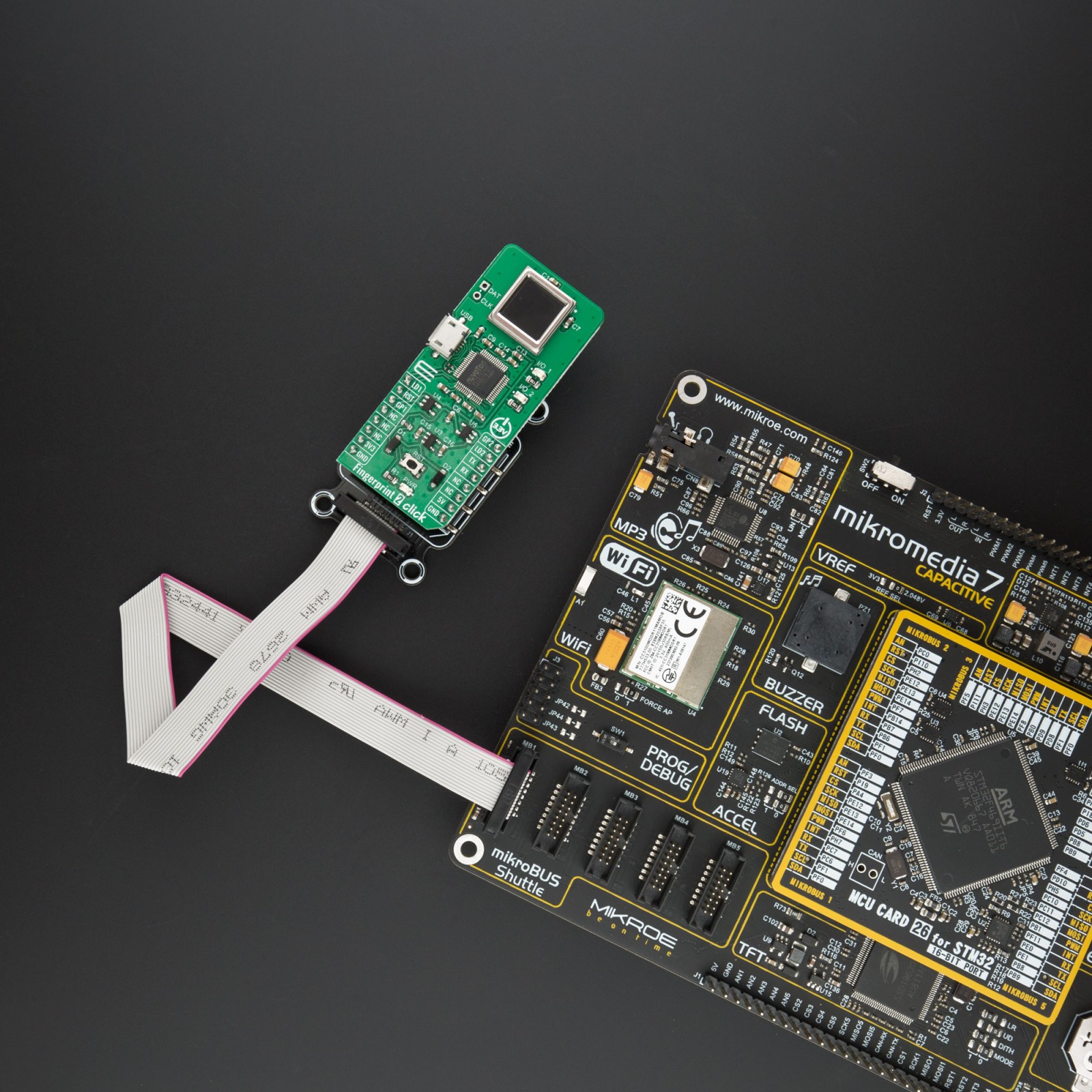
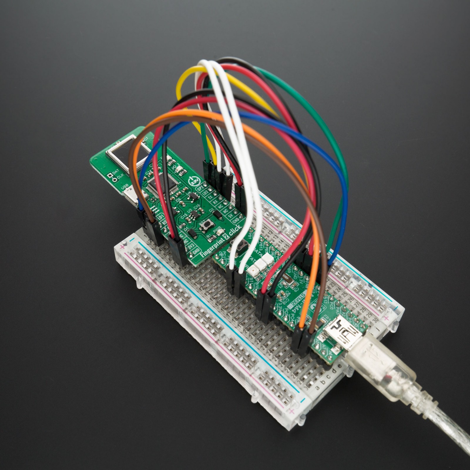
For using and controlling Fingerprint 2 Click with PC Application from ByNew you will need first to connect your board to PC by using USB or some TTL converter for UART. After that you can start Utility tool BNQuickick.exe and select the COM port and Baud rate to operate/control this board.
Since this application is simplifying testing our board and acts as MCU host you can use the same commands from Fingerprint 2 Click example to control our board.
Specifications
Type
Fingerprint
Applications
Fingerprint scanners are chiefly used in biometric security applications
On-board modules
A-172-MRQ-K05A13001, Fingerprint scanners from ByNew
Key Features
8.8×8.8mm active scanning area, capable of storing up to 24 different fingerprints at the same time, as well as recognition algorithm for fingerprint comparison
Interface
GPIO,UART,USB
Feature
No ClickID
Compatibility
mikroBUS™
Click board size
L (57.15 x 25.4 mm)
Input Voltage
3.3V,5V
Pinout diagram
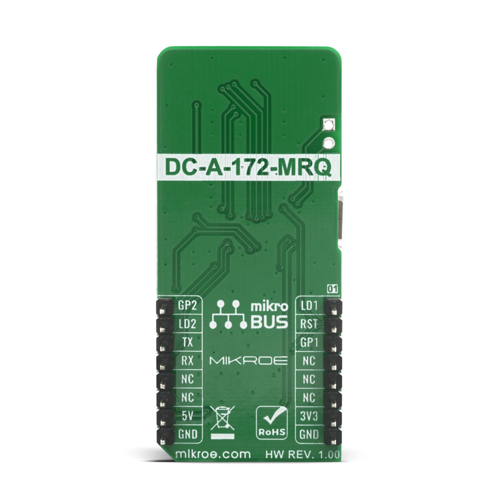
This table shows how the pinout on Fingerprint 2 Click corresponds to the pinout on the mikroBUS™ socket (the latter shown in the two middle columns).
Onboard settings and indicators
Label | Name | Default | Description |
---|---|---|---|
LD1 | PWR | – | Power LED indicator |
LD2 | I/O_1 | – | Compare LED indicator (Green LED) |
LD3 | I/O_2 | – | Compare LED indicator (Red LED) |
T1 | RST | – | Reset button for the MCU |
On Board LED’s
The red and green LEDs flash in turn:
- It indicates in the status of the received command from master.
The red LED and the green LED are ON (light) at the same time:
- It is a temporary state, it will enter the registration state after two or three seconds.
The red LED flashes:
In the registration state, waiting for the user to enroll his fingerprint to register, it can register at most 24 fingerprints, each fingerprint needs to be enrolled 3 times. After each successful enroll of the fingerprint, the green LED will light for two or three seconds.
The green LED flashes:
- In the registration state, waiting for the user to enroll his fingerprint to register, it can register at most 24 fingerprints, each fingerprint needs to be enrolled 3 times. After each successful enroll of the fingerprint, the green LED will light for two or three seconds.
The red LED and the green LED flash twice in turn:
- It indicates the fingerprint image is uploading to master.
Software Support
We provide a library for the Fingerprint 2 Click on our LibStock page, as well as a demo application (example), developed using MikroElektronika compilers. The demo can run on all the main MikroElektronika development boards.
Library Description
Library provides functions for sending commands to device and controlling it’s pins
Key functions:
void fingerprint2_soft_reset ( void )
– Function for reseting devicevoid fingerprint2_send_cmd ( uint8_t *cmd )
– Function for sending command to devicevoid fingerprint2_reg_one_fp ( uint8_t fp_index )
– Function for registrating one fingerprint on specific index
Examples description
The application is composed of three sections :
- System Initialization – Initialization of UART module and additional pins
- Application Initialization – UART interrupt initialization, restarts device and waits for device to exit demo mode
- Application Task – Waits for command to execute code
void application_task ( ) { termianl_read( ); fingerprint2_log( &log_write ); }
Additional Functions :
- void interrupt_init ( ) – UART interrupt initialization.
- void log_write ( uint8_t *str_buf, uint8_t str_type ) – Wrapper fucntion for driver.
- void termianl_read ( ) – Function for reading commands from terminal.
- void send_cmd ( char *cmd_buf ) – Function for compareing string to predefined commands and if match sending commands to device.
- void fp_reg_one ( ) – Function for registering fingerprint on specific index
- void fp_clr_one ( ) – Function for deleteing fingerprint on specific index
Note :
- Commands for terminal:
- reg – to register one fingerprint
- del – to delete one fingerprint
- cmp – to compare fingeprint to data base
- num – to get number of registerd fingerprints
- fw – to get firmware version of device
- ds – to get device status of device
The full application code, and ready to use projects can be found on our LibStock page.
Other mikroE Libraries used in the example:
- UART
- Conversions
Additional notes and informations
Depending on the development board you are using, you may need USB UART click, USB UART 2 click or RS232 click to connect to your PC, for development systems with no UART to USB interface available on the board. The terminal available in all MikroElektronika compilers, or any other terminal application of your choice, can be used to read the message.
mikroSDK
This Click board™ is supported with mikroSDK – MikroElektronika Software Development Kit. To ensure proper operation of mikroSDK compliant Click board™ demo applications, mikroSDK should be downloaded from the LibStock and installed for the compiler you are using.
For more information about mikroSDK, visit the official page.