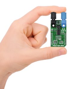
How does it work?
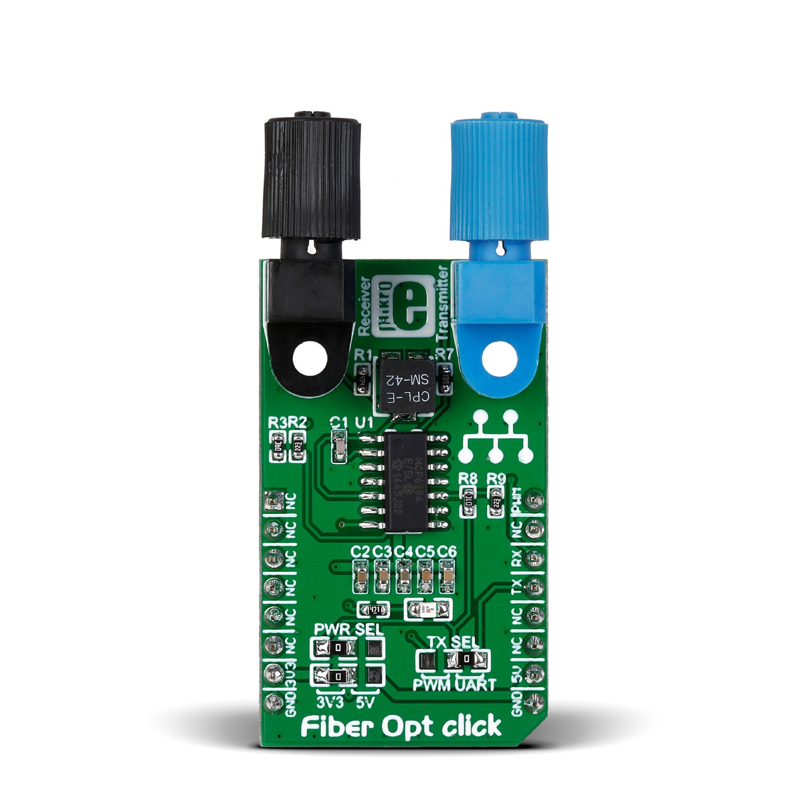
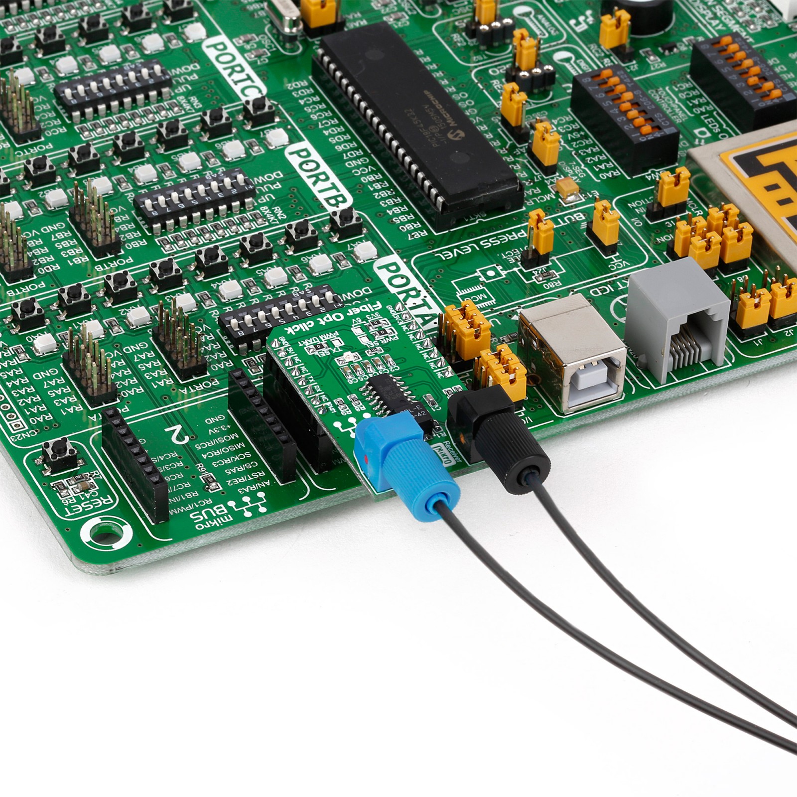
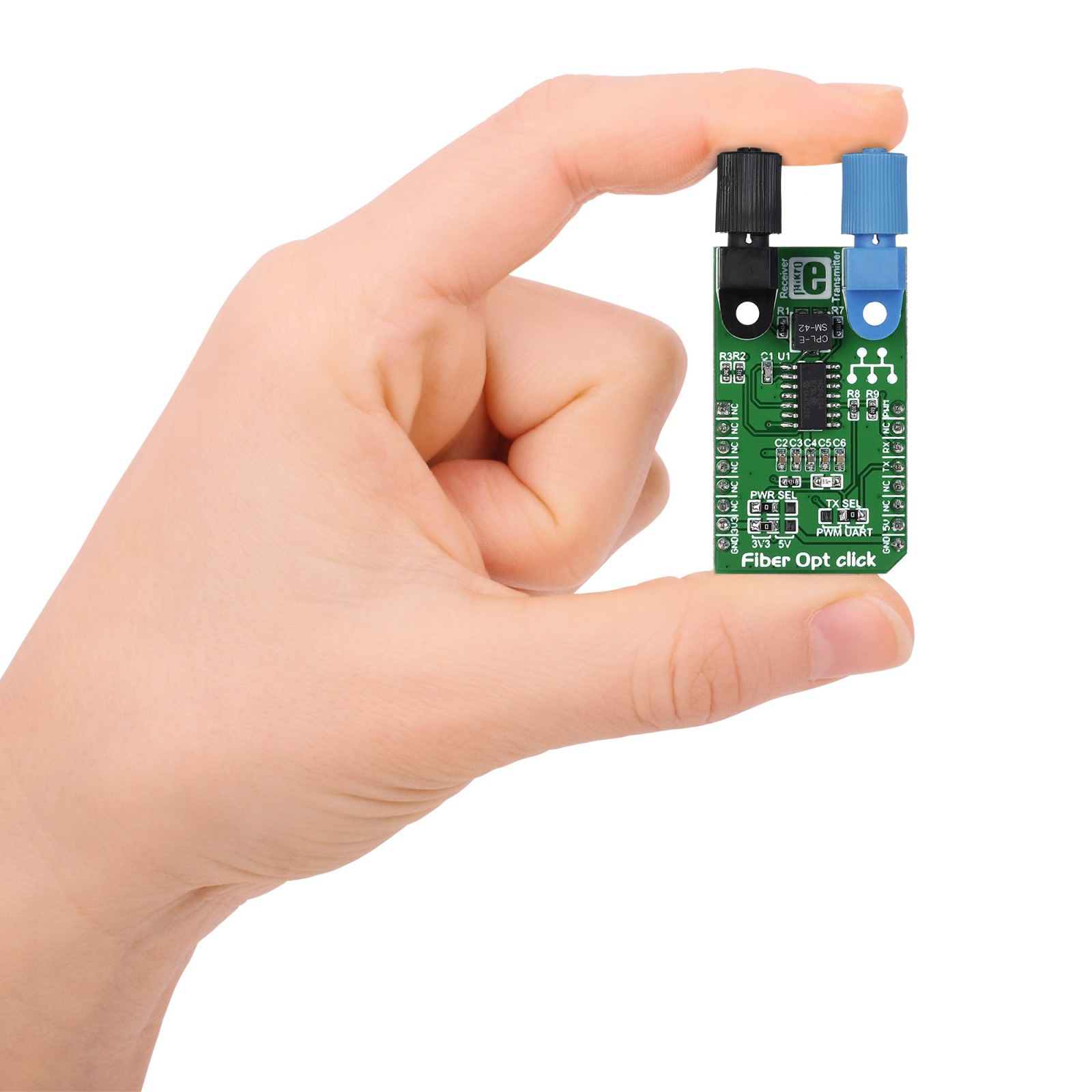
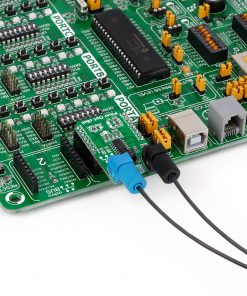
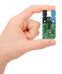
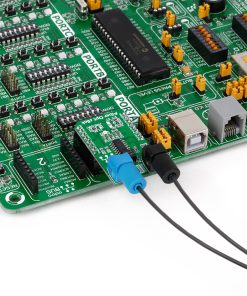
Fiber Opt Click is based on one IF-D91, a fiber-optic photodiode, and one IF-E97, a fiber-optic LED, both from Industrial Fiber Optics. The IF-D91 is a high-speed photodiode detector housed in a connector-less plastic fiber optic package. Its optical response extends from 400 to 1100nm, making it compatible with a wide range of visible and near-infrared LED and laser diode sources. The detector package features an internal micro-lens and a precision-molded PBT housing to ensure efficient optical coupling with standard 1000μm core 2.2mm jacketed plastic fiber cable capable of 100Mbps data rates. The IF-D91 can also be used for analog video links with bandwidths up to 70MHz.
The other precision-molded PBT housing with internal micro-lens, the IF-E97, is a high-optical-output visible red LED. The housing ensures efficient optical coupling with the same standard jacketed plastic fiber cable. The output spectrum is produced by a GaAlAs die, which peaks at 650nm, representing an optimal transmission window for PMMA plastic optical fiber. The visible red light has low attenuation in PMMA plastic fiber, aids troubleshooting installations, and is the main reason the IF-E97 achieves data rates of 1Mbps.
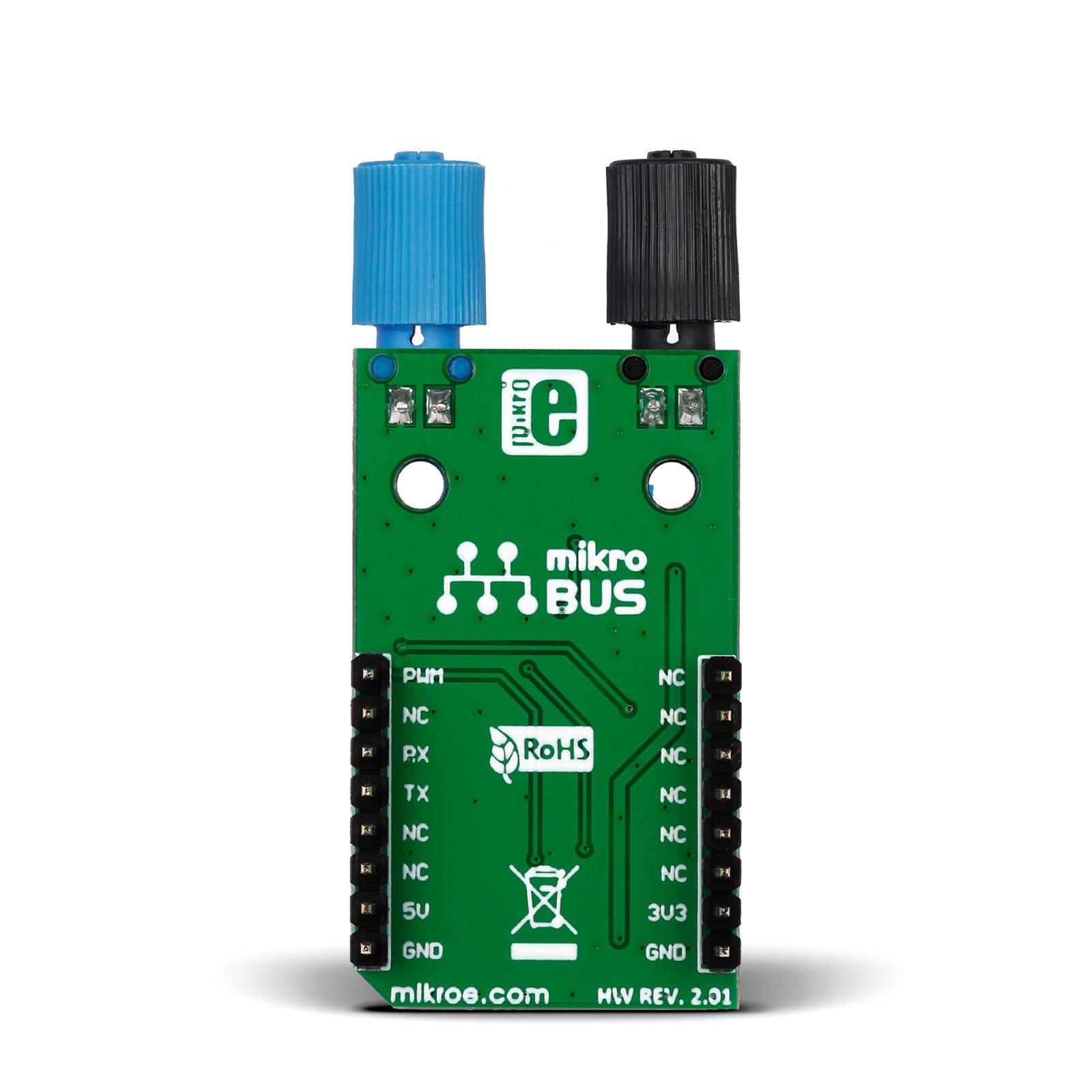
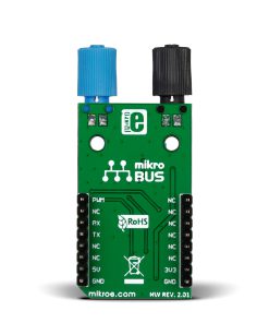
This Click board™ communicates with the host MCU over selectable pins of the mikroBUS™ socket. Transmission can be selected through the TX SEL selection jumper between the UART TX pin or PWM pin of the mikroBUS™ socket, as UART is selected by default. Received data is available on the RX pin of the mikroBUS™ socket.
This Click board™ can operate with either 3.3V or 5V logic voltage levels selected via the PWR SEL jumper. This way, both 3.3V and 5V capable MCUs can use the communication lines properly. Also, this Click board™ comes equipped with a library containing easy-to-use functions and an example code that can be used, as a reference, for further development.
Specifications
Type
Fiber optics
Applications
Board is ideal for data links, local area networks, motor controller triggering, medical instruments, EMC/EMI signal isolation and many moreCan be used for high-speed digital data links, local area networks, video links, EMC/EMI signal isolation, fiber optic modems, and more
On-board modules
IF-D91 – fiber-optic photodiode from Industrial Fiber Optics
IF-E97 – fiber-optic LED from Industrial Fiber Optics
MCP6284 – dual operational amplifier from Microchip
Key Features
High optical power, internal micro-lens for efficient optical coupling, no interference, connector-less fiber termination, mates with standard 1000μm core and 2.2mm jacketed plastic fiber cable, low transmission loss, and more
Interface
PWM,UART
Feature
No ClickID
Compatibility
mikroBUS™
Click board size
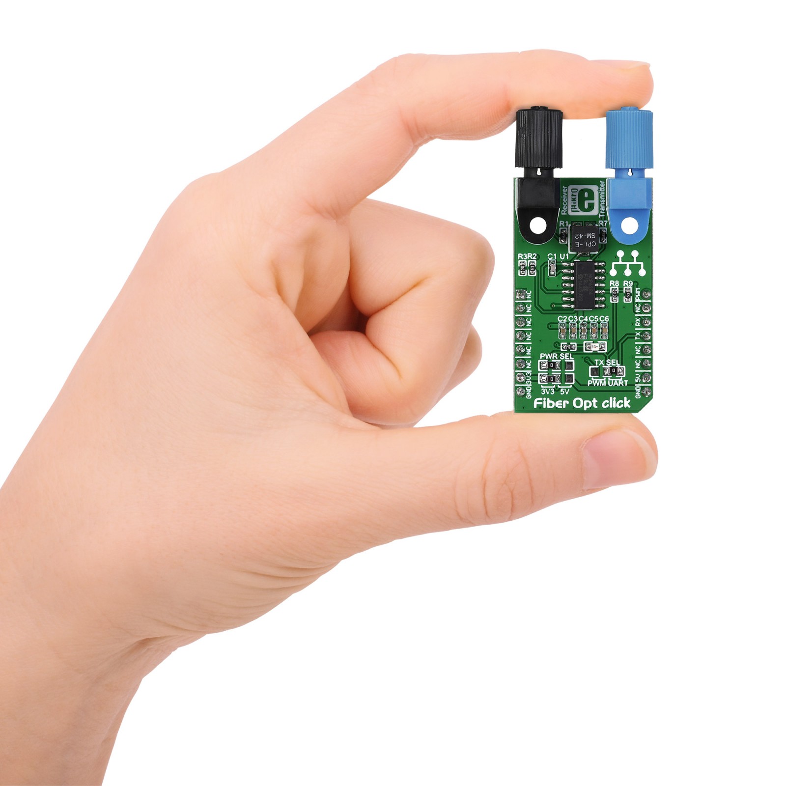
M (42.9 x 25.4 mm)
Input Voltage
3.3V or 5V
Pinout diagram
This table shows how the pinout on Fiber Opt Click corresponds to the pinout on the mikroBUS™ socket (the latter shown in the two middle columns).
Onboard settings and indicators
Label | Name | Default | Description |
---|---|---|---|
LD1 | PWR | – | Power LED Indicator |
J1-J2 | TX SEL | Right | Communication Lines Selection PWM/UART: Left position PWM, Right position UART |
Fiber Opt Click electrical specifications
Description | Min | Typ | Max | Unit |
---|---|---|---|---|
Supply Voltage | 3.3 | – | 5 | V |
Output Spectrum Peak | – | 650 | – | nm |
Output Data Rate | – | 1 | – | Mbps |
Input Data Rate | – | 100 | – | Mbps |
Software Support
We provide a library for the Fiber Opt Click as well as a demo application (example), developed using MIKROE compilers. The demo can run on all the main MIKROE development boards.
Package can be downloaded/installed directly from NECTO Studio Package Manager (recommended), downloaded from our LibStock™ or found on Mikroe github account.
Library Description
This library contains API for Fiber Opt Click driver.
Key functions
-
fiberopt_generic_write
Generic single write function. -
fiberopt_generic_read
Generic single read function.
Example Description
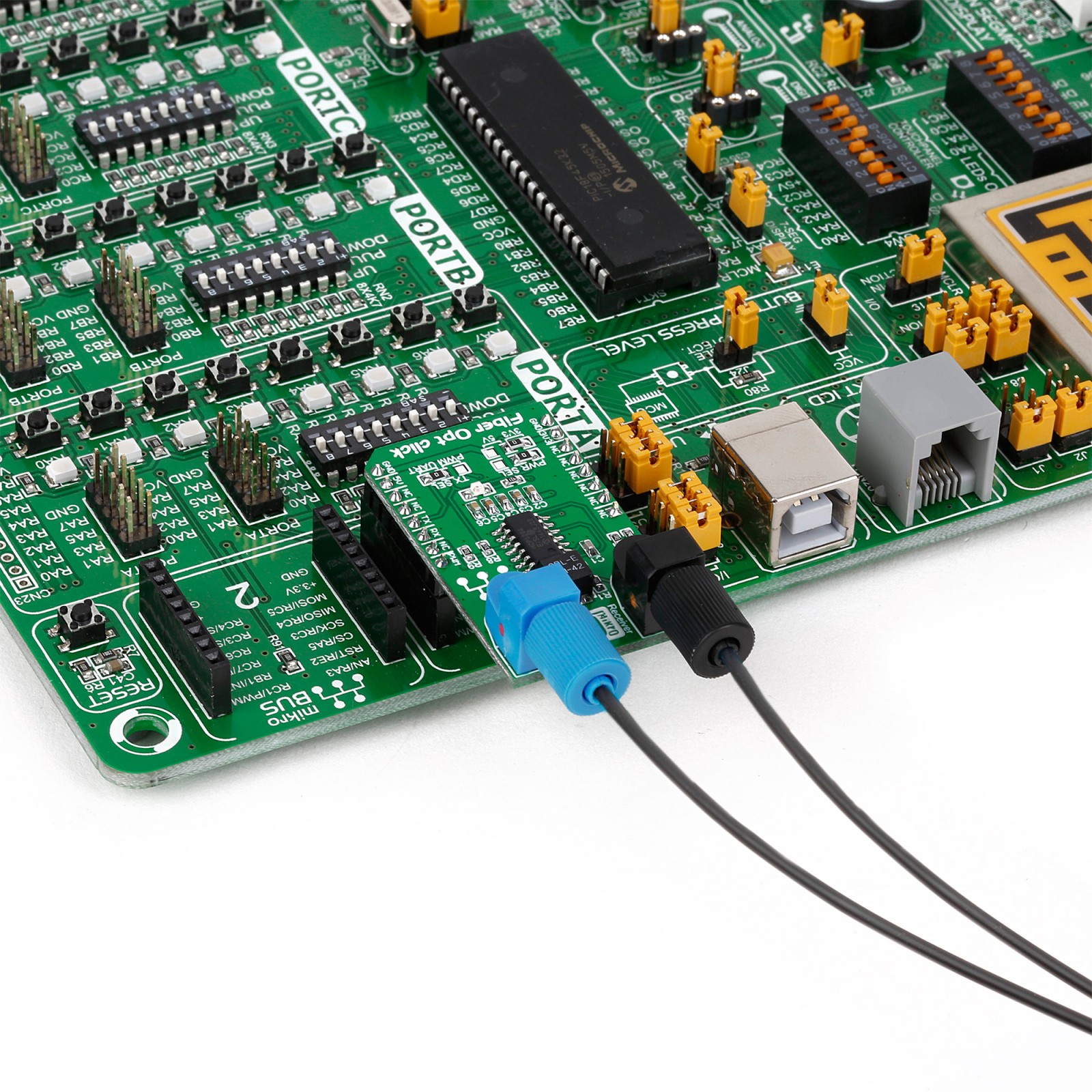
This example demonstrates the use of an Fiber Opt click board by showing the communication between the two click boards.
void application_task ( void )
{
#ifdef DEMO_APP_TRANSMITTER
fiberopt_generic_write( &fiberopt, DEMO_TEXT_MESSAGE, strlen( DEMO_TEXT_MESSAGE ) );
log_printf( &logger, "%s", ( char * ) DEMO_TEXT_MESSAGE );
Delay_ms( 1000 );
#else
uint8_t rx_byte = 0;
if ( 1 == fiberopt_generic_read( &fiberopt, &rx_byte, 1 ) )
{
log_printf( &logger, "%c", rx_byte );
}
#endif
}
The full application code, and ready to use projects can be installed directly from NECTO Studio Package Manager (recommended), downloaded from our LibStock™ or found on Mikroe github account.
Other Mikroe Libraries used in the example:
- MikroSDK.Board
- MikroSDK.Log
- Click.FiberOpt
Additional notes and informations
Depending on the development board you are using, you may need USB UART click, USB UART 2 Click or RS232 Click to connect to your PC, for development systems with no UART to USB interface available on the board. UART terminal is available in all MIKROE compilers.
mikroSDK
This Click board™ is supported with mikroSDK – MIKROE Software Development Kit. To ensure proper operation of mikroSDK compliant Click board™ demo applications, mikroSDK should be downloaded from the LibStock and installed for the compiler you are using.
For more information about mikroSDK, visit the official page.