EXPAND 5 Click
R245.00 ex. VAT
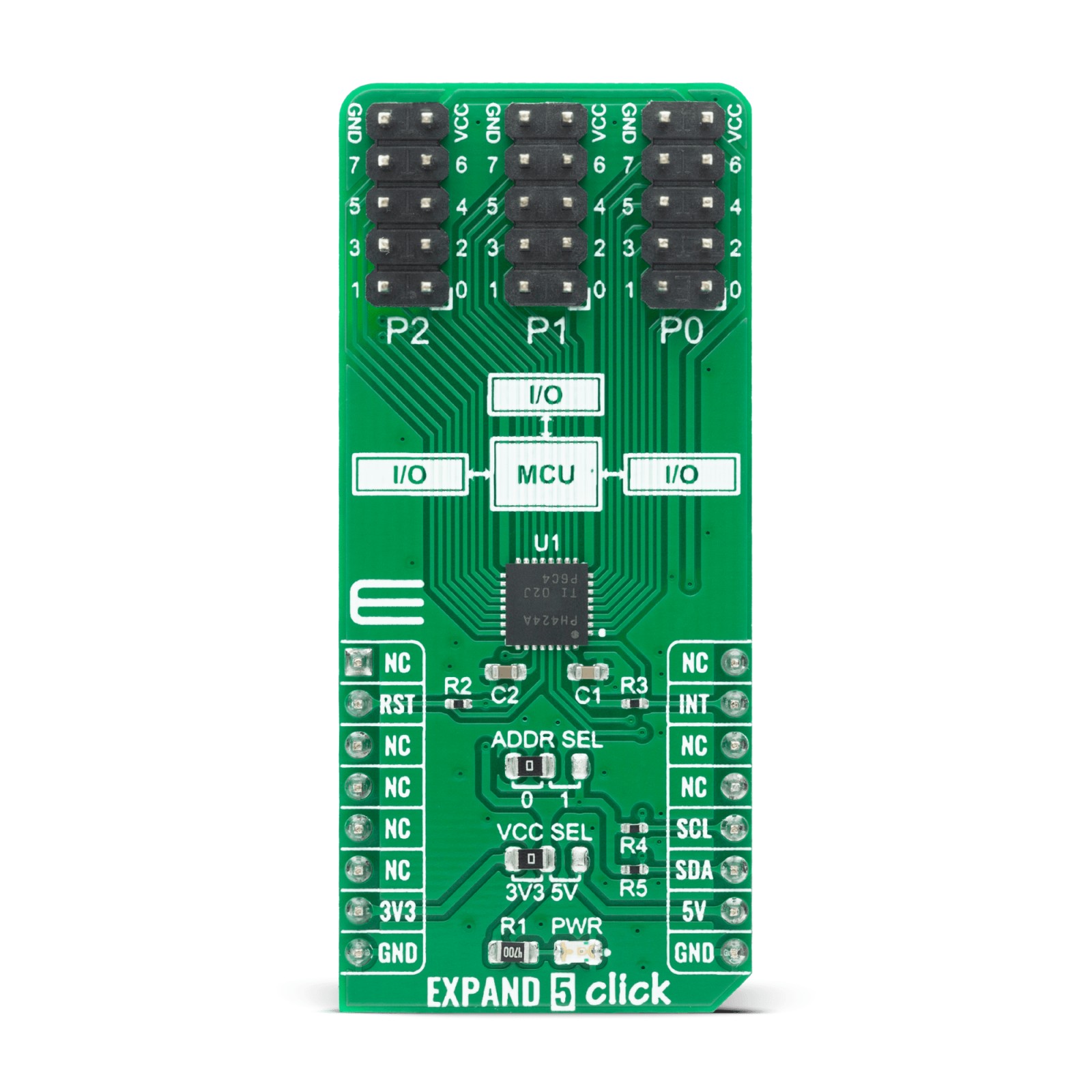
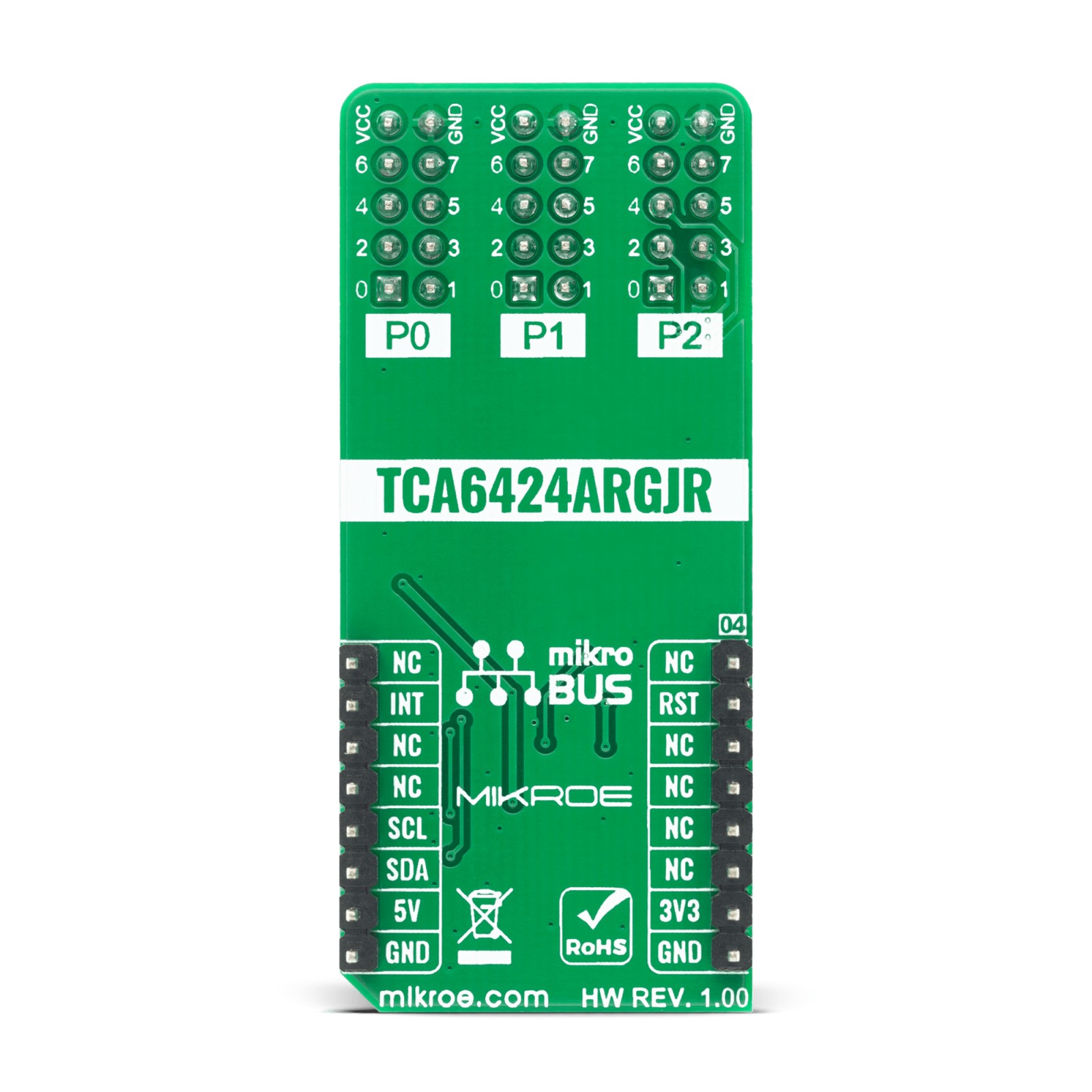
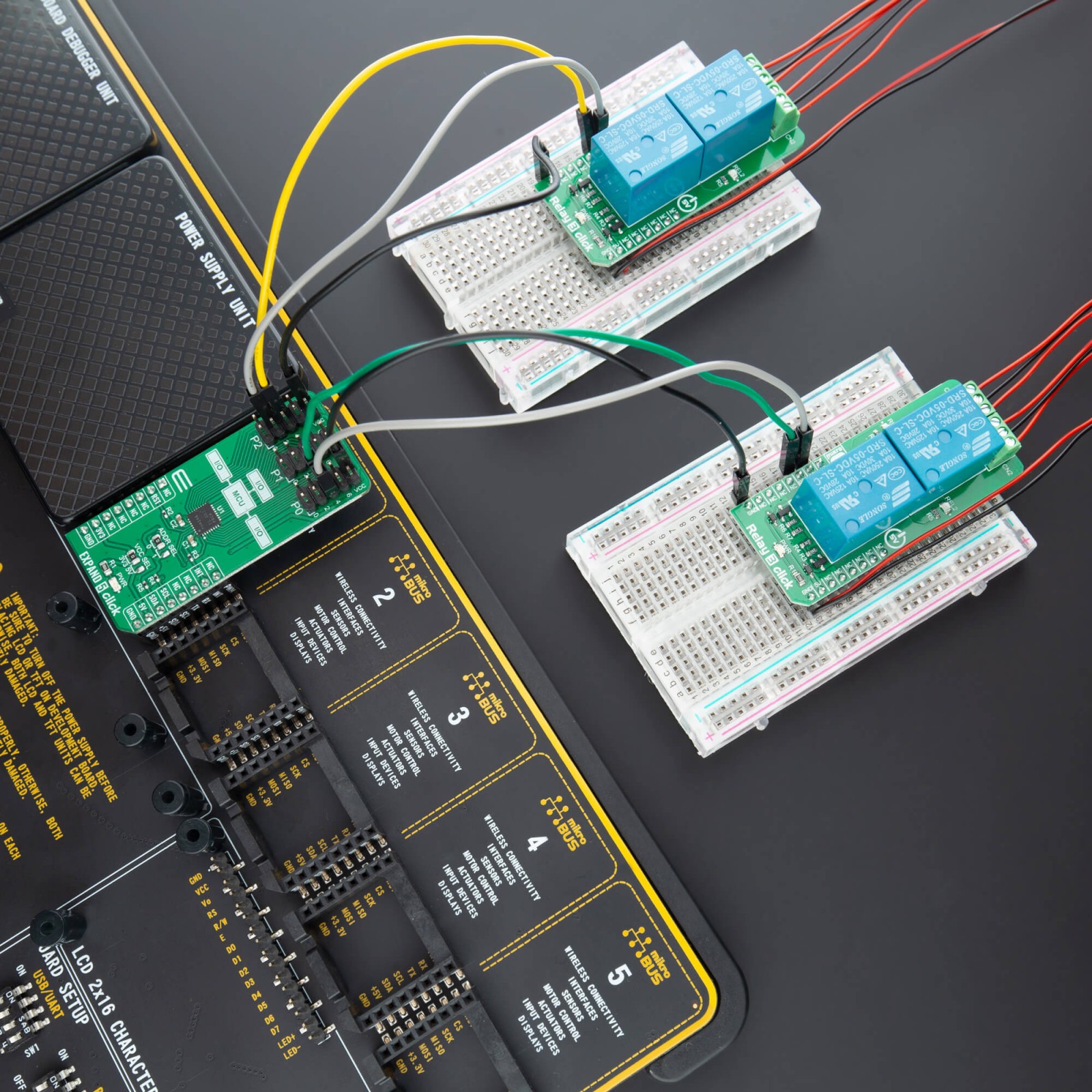
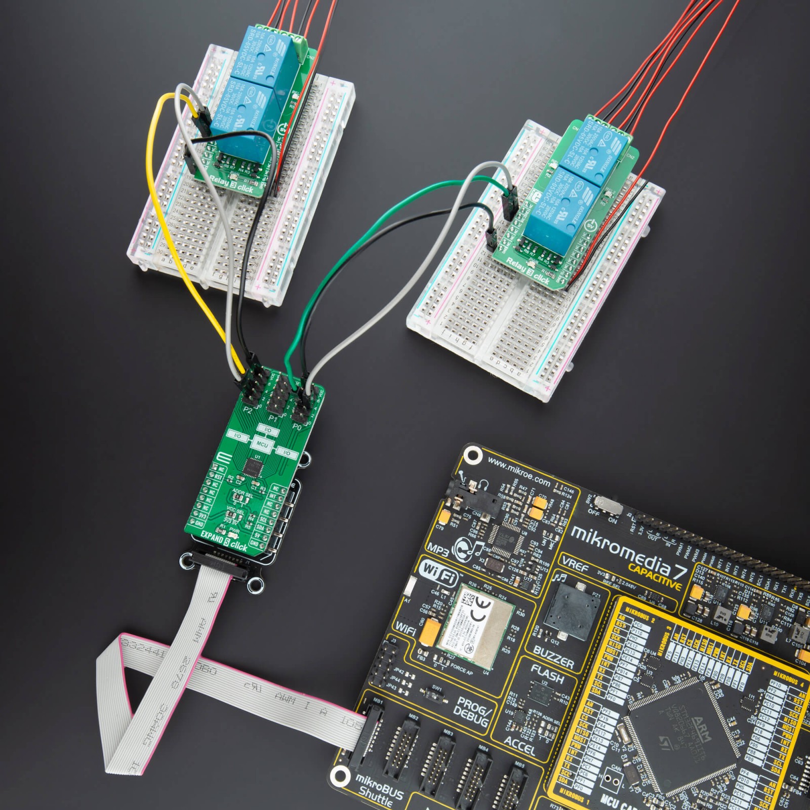
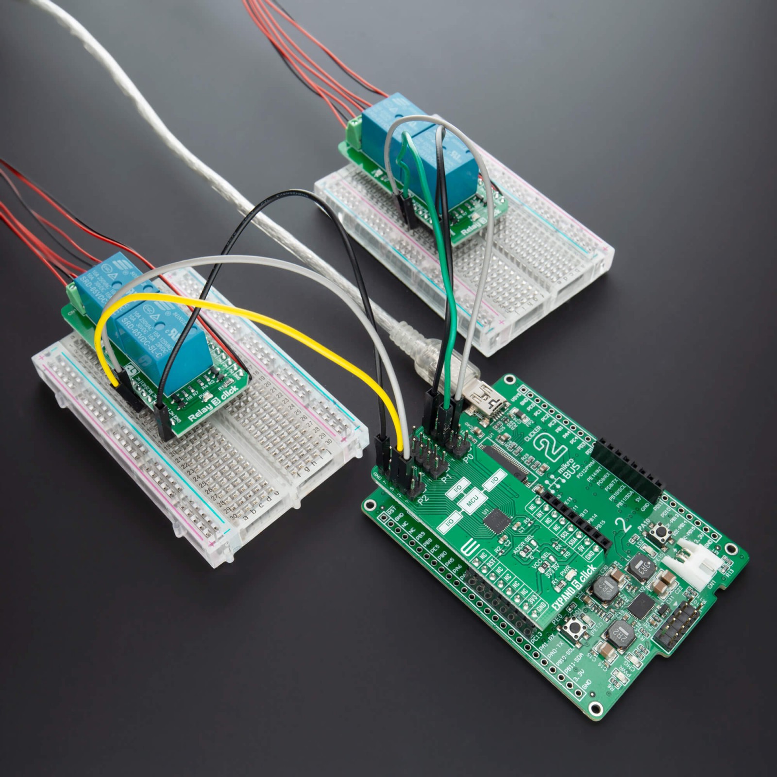
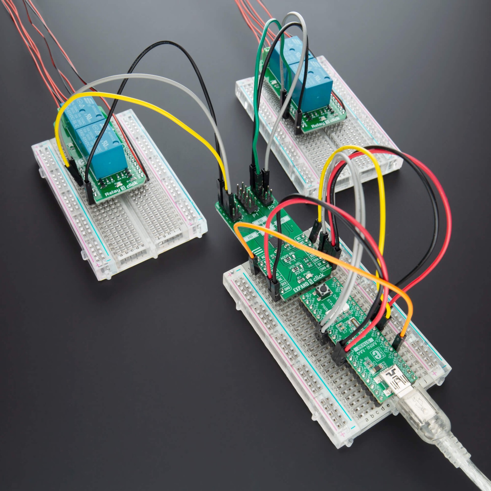
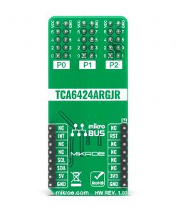
EXPAND 5 Click features a low-voltage 24-bit I2C and SMBus I/O expander. This 24-bit I/O expander is designed to provide general-purpose remote I/O expansion for most microcontroller families via the I2C serial interface. This Click board™ features the TCA6424A from Texas Instruments, and it operates over a power supply voltage range of 1.65V to 5.5V. Wide voltage range allows the TCA6424A to interface with next-generation microprocessors and microcontrollers on the SDA/SCL side, where supply levels are dropping down to conserve power. The P-port outputs have high-current sink capabilities for directly driving LEDs while consuming low device current.
EXPAND 5 Click is supported by a mikroSDK compliant library, which includes functions that simplify software development. This Click board™ comes as a fully tested product, ready to be used on a system equipped with the mikroBUS™ socket.
Stock: Lead-time applicable.
| 5+ | R232.75 |
| 10+ | R220.50 |
| 15+ | R208.25 |
| 20+ | R200.41 |
How does it work?
EXPAND 5 Click uses the TCA6424A IC, low-voltage 24-bit I2C, and SMBus I/O expander from Texas Instruments. This 24-bit I/O expander for the two-line bidirectional bus is designed to provide general-purpose remote I/O expansion for most microcontroller families via the 400-kHz fast I2C bus. This Click board™ features on-board I2C address jumpers, pull-up resistors, power supply bypass capacitor, and power LED. It operates over a flexible power supply voltage range of 1.65V to 5.5V, which makes it suitable for 3.3V and 5V microcontrollers.

At power-on, the I/O pins are configured as inputs. However, the microcontroller can enable the I/Os as either inputs or outputs by writing to the I/O configuration bits. The data for each input or output is kept in the corresponding input or output register. The polarity of the Input Port register can be inverted with the Polarity Inversion register. The microcontroller can reset the TCA6424A in the event of a timeout or other improper operation by asserting a low in the RESET input. The power-on reset puts the registers in their default state and initializes the I2C interface. The RESET pin causes the same reset/initialization to occur without depowering the part. This Click board™ also has an open-drain interrupt (INT) output that is activated when any input state differs from its corresponding Input Port register state and is used to indicate to the microcontroller that an input state has changed. By sending an interrupt signal on this line, the remote I/O can inform the microcontroller if there is incoming data on its ports without having to communicate via the I2C bus. Thus, the TCA6424A can remain a simple slave device.
The TCA6424A communicates with MCU using the standard I2C 2-wire interface. The TCA6424A can respond to one of two 7-bit I2C Bus Slave addresses. The first 6 bits (MSBs) have been factory programmed to 010001. The address pin, ADDR (Pin 26) is programmed by the user and determines the LSB of the slave address and it can be selected by onboard SMD jumper labeled as ADDR SEL allowing selection of the slave address LSB. The last bit of the slave address defines the operation (read or write) to be performed. A high (1) selects a read operation, while a low (0) selects a write operation.
This Click board™ can be supplied and interfaced with both 3.3V and 5V without the need for any external components. The onboard SMD jumper labeled as VCC SEL allows voltage selection for interfacing with both 3.3V and 5V microcontrollers. More information about the TCA6424A can be found in the attached datasheet. However, this Click board™ comes equipped with a library that contains easy to use functions and a usage example that may be used as a reference for the development.
Specifications
Type
Port expander
Applications
Can be used to provide general-purpose remote I/O expansion for most microcontroller families via the I2C serial interface.
On-board modules
TCA6424A
Key Features
24-bit, 400-kHz I2C port expander, wide voltage range, high-current sink outputs
Interface
GPIO,I2C
Feature
No ClickID
Compatibility
mikroBUS™
Click board size
L (57.15 x 25.4 mm)
Input Voltage
3.3V or 5V
Pinout diagram
Onboard settings and indicators
| Label | Name | Default | Description |
|---|---|---|---|
| LD1 | PWR | – | Power LED Indicator |
| JP1 | VCC SEL | Left | Power Supply Voltage Selection 3V3/5V, left position 3V3, right position 5V |
| JP2 | ADDR SEL | Left | I2C Address selection: Left position 0, Right position 1 |
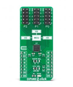
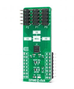
| J1-J3 | P0-P2 Port | – | I/O Expander Ports |
Spectrometer Click electrical specifications
| Description | Min | Typ | Max | Unit |
|---|---|---|---|---|
| Supply Voltage | -0.5 | – | 6.5 | V |
| Maximum Output Current | – | – | 25 | mA |
| Maximum Frequency | – | – | 400 | kHz |
| Operating Temperature Range | -40 | – | +85 | °C |
Software Support
We provide a library for the EXPAND 5 Click on our LibStock page, as well as a demo application (example), developed using MikroElektronika compilers. The demo can run on all the main MikroElektronika development boards.
Library Description
The library covers necessary functions that enables the usage of the EXPAND 5 click board. User can configure polarity and direction of every pin and get or set state of each and every pin.
Key functions:
void expand5_set_all_dir( uint8_t bank0, uint8_t bank1, uint8_t bank2 );– Function is used to set pins’ direction ( I/O ) setting in all banks.void expand5_write_pin ( uint16_t pin, uint8_t pin_val );– Function is used to set a single output pin’s logic level.void expand5_write_all_banks ( uint8_t bank0, uint8_t bank1, uint8_t bank2 );– Function is used to set logic levels in all banks.
Examples description
The application is composed of three sections :
- System Initialization – Initializes I2C module, LOG structure and sets RST pin as output and INT pin as input.
- Application Initialization – Initalizes I2C driver, resets the device, configures all pins as output and makes an initial log.
- Application Task – (code snippet) This example shows the capabilities of the EXPAND 5 click by toggling each of 24 available pins.
void application_task ( )
{
    for ( pin_num = EXPAND5_P00; pin_num <= EXPAND5_P27; pin_num++ )
    {
        expand5_write_all_banks ( bank_low, bank_low, bank_low );
        expand5_write_pin ( pin_num, EXPAND5_HIGH );
        mikrobus_logWrite( "Pin ", _LOG_TEXT );
        ByteToStr( pin_num, log_txt );
        Ltrim( log_txt );
        mikrobus_logWrite( log_txt, _LOG_TEXT );
        mikrobus_logWrite( " is high!", _LOG_LINE );

        Delay_ms( 100 );
        expand5_write_all_banks ( bank_low, bank_low, bank_low );
    }
    mikrobus_logWrite( "-------------------", _LOG_LINE );
    Delay_ms( 1000 );
}
The full application code, and ready to use projects can be found on our LibStock page.
Other mikroE Libraries used in the example:
- I2C
- UART
- Conversions
Additional notes and informations
Depending on the development board you are using, you may need USB UART click, USB UART 2 click or RS232 click to connect to your PC, for development systems with no UART to USB interface available on the board. The terminal available in all MikroElektronika compilers, or any other terminal application of your choice, can be used to read the message.
mikroSDK
This Click board™ is supported with mikroSDK – MikroElektronika Software Development Kit. To ensure proper operation of mikroSDK compliant Click board™ demo applications, mikroSDK should be downloaded from the LibStock and installed for the compiler you are using.
For more information about mikroSDK, visit the official page.
Resources
Downloads
| Weight | 25 g |
|---|---|
| Brand | MikroElektronika |

