How does it work?
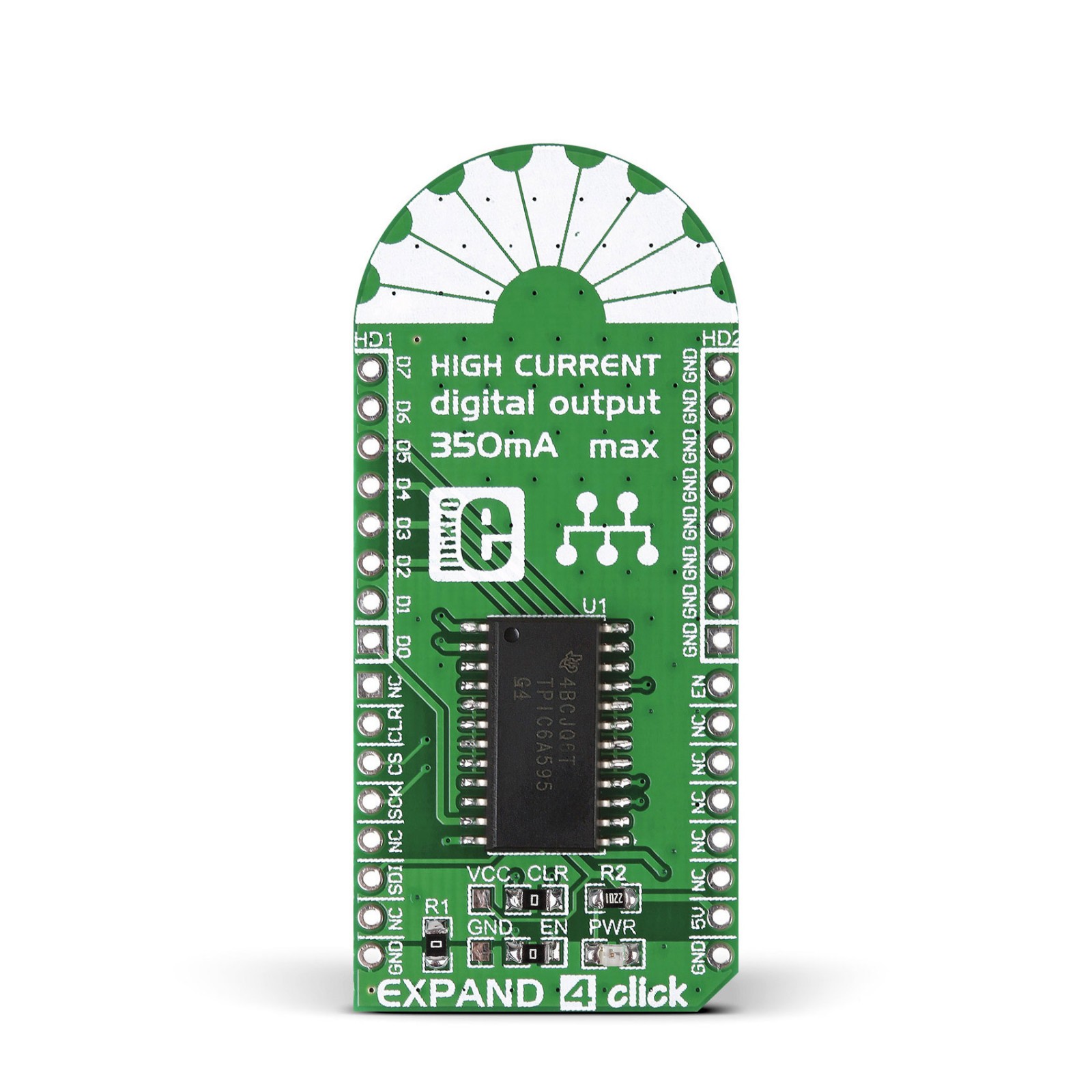
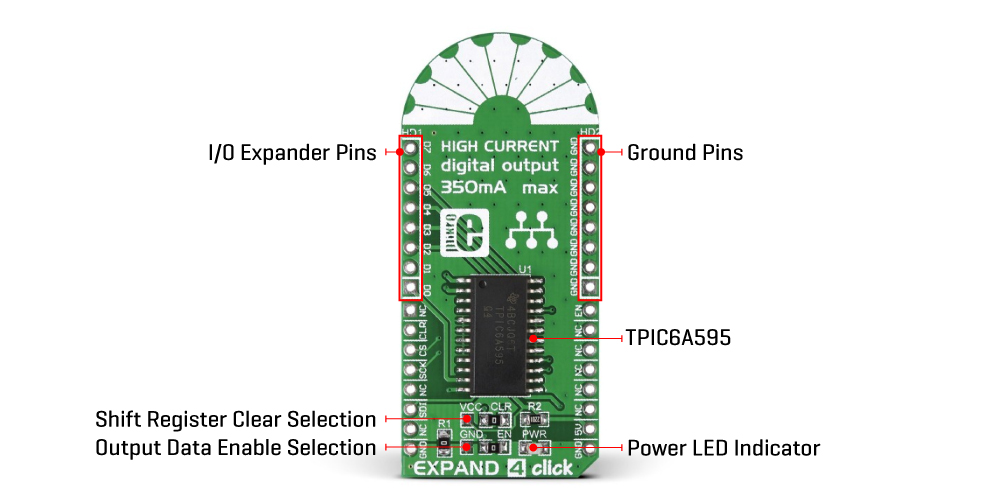
Expand 4 Click is based on the TPIC6A595, a monolithic, high-voltage, high-current power logic 8-bit shift register from Texas Instruments. The TPIC6A595 contains a built-in voltage clamp on the outputs for inductive transient protection. Each output is a low-side, open-drain DMOS transistor with output ratings of 50V and a 350mA continuous sink current capability, featuring an independent chopping current-limiting circuit to prevent damage in the case of a short circuit. This Click board™ is designed for use in systems that require relatively high load power, such as relays, solenoids, and other medium-current or high-voltage loads.
This TPIC6A595 contains an 8-bit serial-in, parallel-out shift register that feeds an 8-bit, D-type storage register. Data transfers through the shift and storage register on the rising edge of the shift register clock (SPI clock pin on the mikroBUS™ socket) and the register clock (CS clock pin on the mikroBUS™ socket), respectively.
The storage register transfers data to the output buffer when the shift register clear pin is set to a high logic state. This function can be done in two ways via the existing CLR jumper by placing it in the appropriate VCC or CLR position. In this way, it is possible to permanently bind this function so that the storage register always transfers data to the output buffer by setting the jumper to the VCC position or controlled digitally by setting the jumper to the CLR position. This way, it is possible to control the shift-register-clear via the RST pin of the mikroBUS™ socket marked as CLR. The input shift register is cleared when CLR is in a low logic state.
In the same way, it is possible to manage the outputs of the port expander, eight pins above the mikroBUS™ socket (D0-D7), using EN jumper, more precisely define the output management mode, constantly ON or digital control over them through PWM pin of the mikroBUS™ socket marked as EN. When the output enable EN pin is held in a high logic state, all data in the output buffers is kept low, and all drain outputs are OFF. When EN is in a low logic state, data from the storage register is transparent to the output buffers.
This Click board™ can be operated only with a 5V logic voltage level. The board must perform appropriate logic voltage level conversion before using MCUs with different logic levels. However, the Click board™ comes equipped with a library containing functions and an example code that can be used as a reference for further development.
Specifications
Type
Port expander
Applications
Can be used in systems that require relatively high load power, such as relays, solenoids, and other medium-current or high-voltage loads
On-board modules
TPCIC6A595 – 8-bit serial-in, parallel-out shift register from Texas Instruments
Key Features
8-bit D-type storage register, built-in voltage clamp on the outputs for inductive transient protection, output enable feature, shift-register-clear selection, eight 350mA DMOS outputs, low power consumption, and more
Interface
GPIO,SPI
Feature
No ClickID
Compatibility
mikroBUS™
Click board size
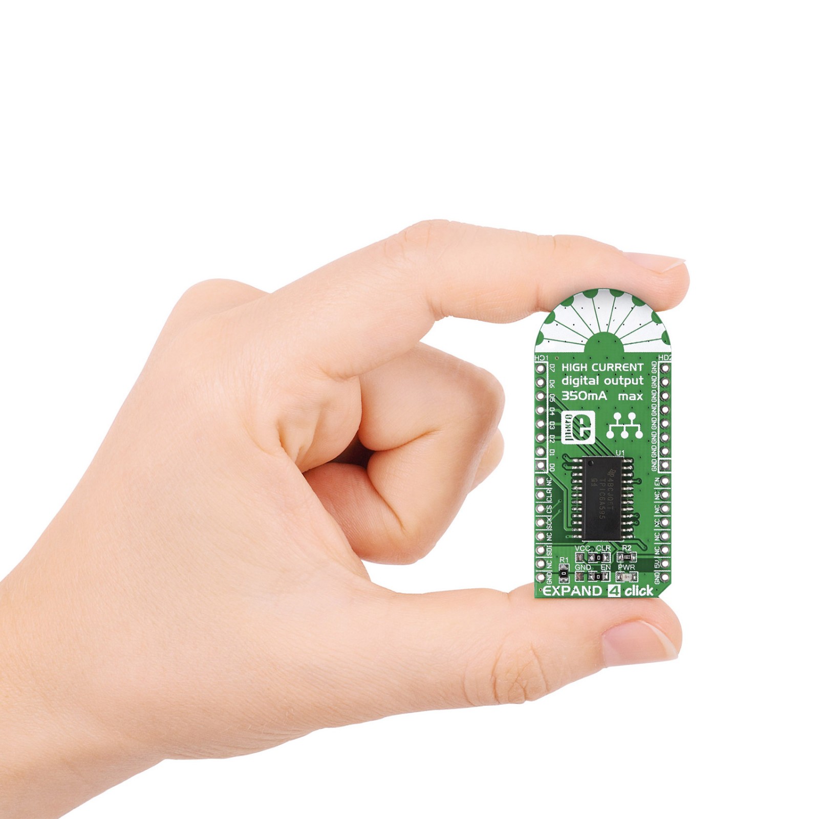
L (57.15 x 25.4 mm)
Input Voltage
5V
Pinout diagram
This table shows how the pinout on EXPAND 4 Click corresponds to the pinout on the mikroBUS™ socket (the latter shown in the two middle columns).
Onboard settings and indicators
Label | Name | Default | Description |
---|---|---|---|
LD1 | PWR | – | Power LED Indicator |
J1 | – | Right | Shift Register Clear Selection VCC/CLR: Left position VCC, Right position CLR |
J2 | – | Right | Output Data Enable Selection GND/EN: Left position GND, Right position EN |
HD1 | HD1 | Unpopulated | I/O Expander Pins Header |
HD2 | HD2 | Unpopulated | Ground Pins Header |
EXPAND 4 Click electrical specifications
Description | Min | Typ | Max | Unit |
---|---|---|---|---|
Supply Voltage | – | 5 | – | V |
Software Support
We provide a library for the Expand 4 Click as well as a demo application (example), developed using Mikroe compilers. The demo can run on all the main Mikroe development boards.
Package can be downloaded/installed directly from NECTO Studio Package Manager(recommended), downloaded from our LibStock™ or found on Mikroe github account.
Library Description
This library contains API for Expand 4 Click driver.
Key functions
-
Function write 8-bit data function to TPIC6A595 shift register.
-
Function turn on output buffers – set PWM pin low
-
Function clear input TPIC6A595 shift register.
Example Description
Example demonstrates use of Expand 4 Click board.
void application_task ( void )
{
uint8_t pin_position;
for ( pin_position = 0; pin_position < 8; pin_position++ )
{
expand4_disable_output( &expand4 );
Delay_ms( 100 );
expand4_turn_on_by_position( &expand4, pin_position );
Delay_ms( 100 );
log_printf( &logger, " D%d", pin_position );
expand4_enable_output( &expand4 );
Delay_ms( 3000 );
}
log_printf( &logger, "n----------------------------------n");
}
The full application code, and ready to use projects can be installed directly from NECTO Studio Package Manager(recommended), downloaded from our LibStock™ or found on Mikroe github account.
Other Mikroe Libraries used in the example:
- MikroSDK.Board
- MikroSDK.Log
- Click.Expand4
Additional notes and informations
Depending on the development board you are using, you may need USB UART click, USB UART 2 Click or RS232 Click to connect to your PC, for development systems with no UART to USB interface available on the board. UART terminal is available in all Mikroe compilers.
mikroSDK
This Click board™ is supported with mikroSDK – Mikroe Software Development Kit. To ensure proper operation of mikroSDK compliant Click board™ demo applications, mikroSDK should be downloaded from the LibStock and installed for the compiler you are using.
For more information about mikroSDK, visit the official page.