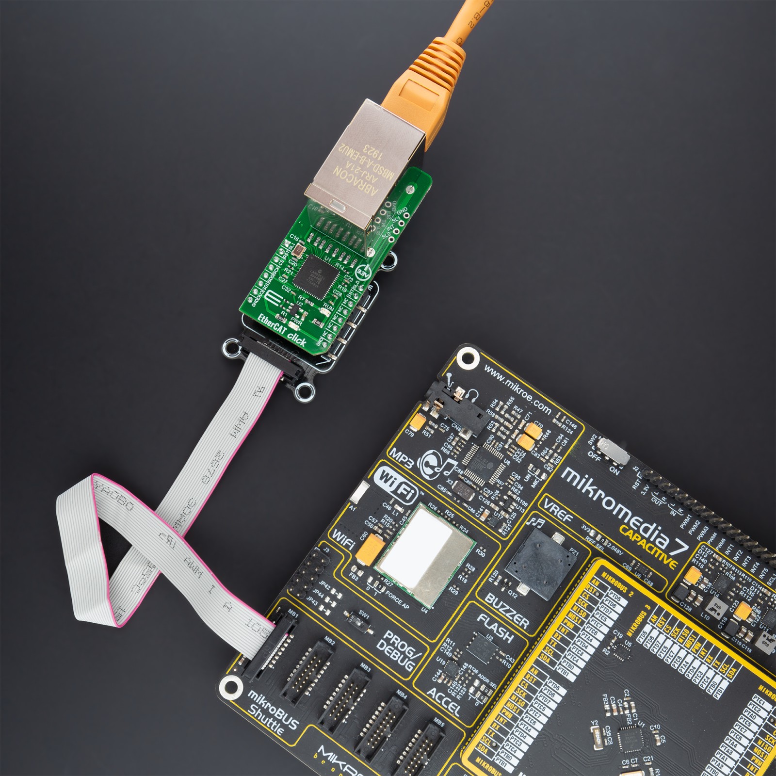
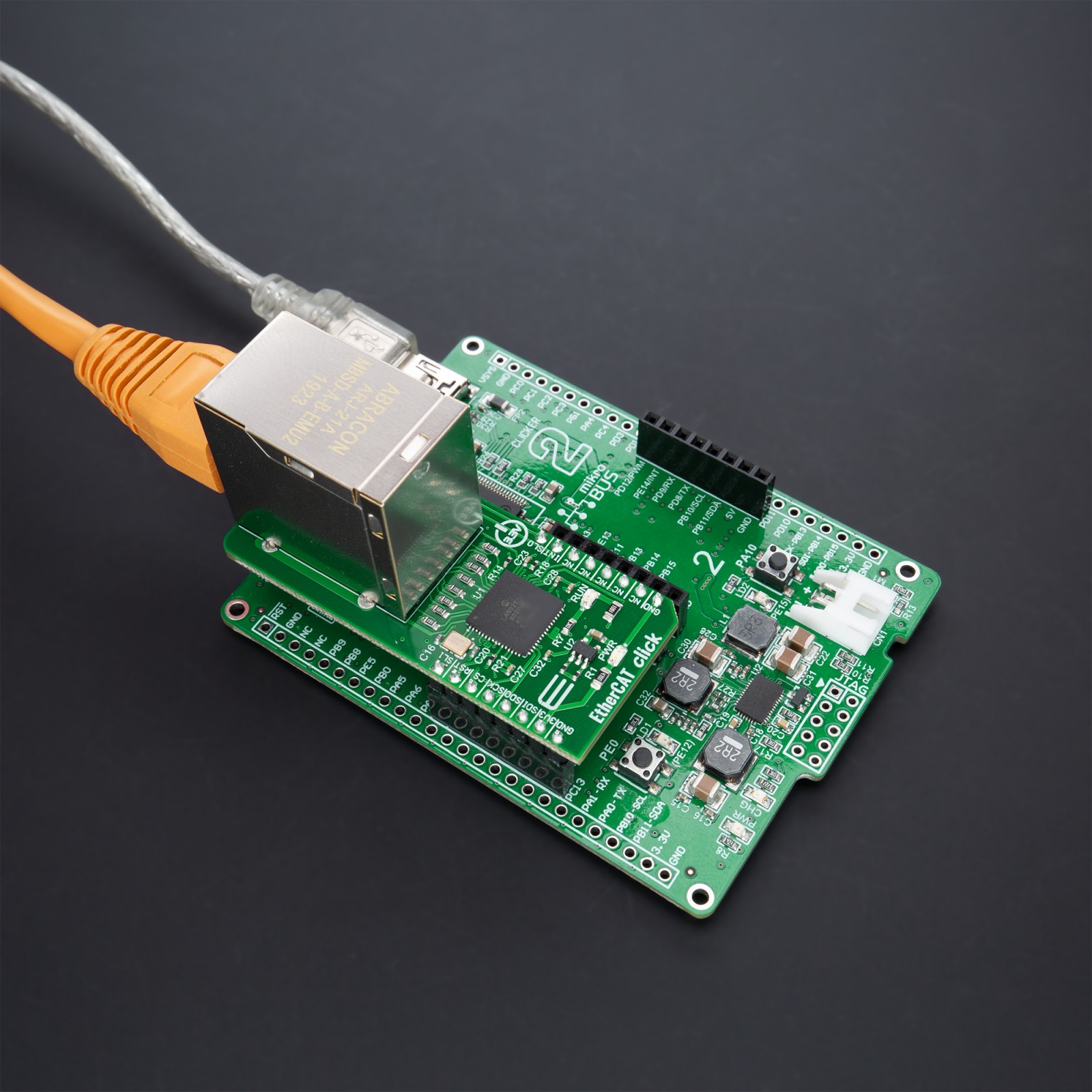
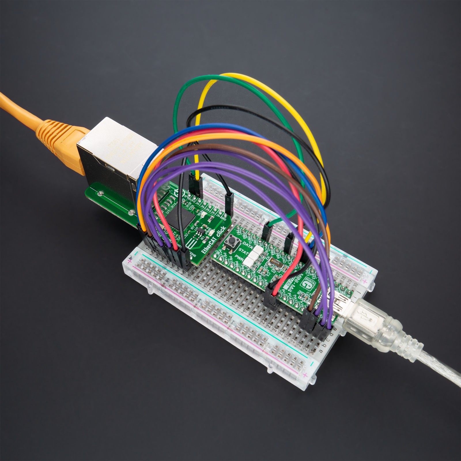
EtherCAT Click
R780.00 ex. VAT
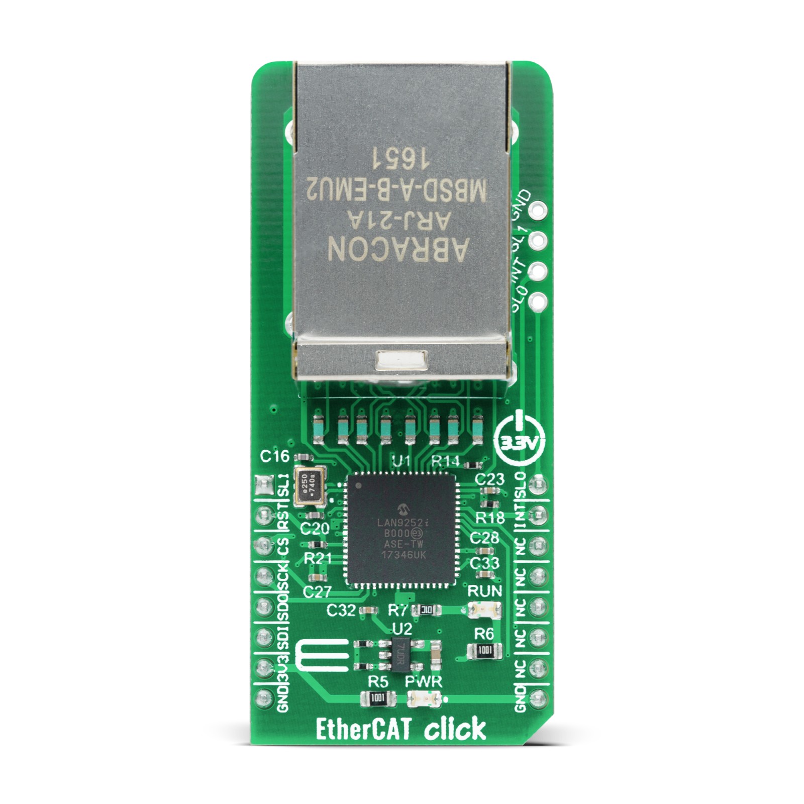
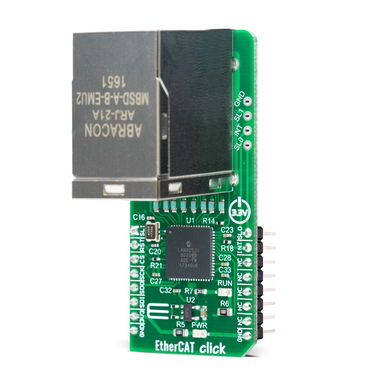
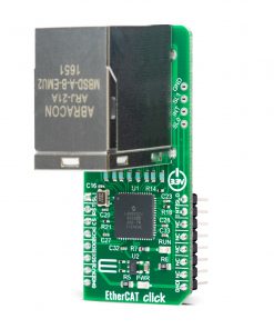
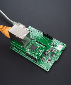
EtherCAT Click is a compact add-on board that provides a cost-effective solution for realizing EtherCAT device solutions on various processors over the SPI interface. This board features the LAN9252, a 2-port EtherCAT device controller with dual integrated Ethernet PHYs from Microchip Technology. Each PHY contains a full-duplex 100BASE-TX transceiver and supports 100Mbps operation. The LAN9252 supports HP Auto-MDIX, allowing the use of direct connects or cross-over LAN cables. It communicates with MCU via a synchronous device SPI/SQI interface and can operate in Digital I/O Mode, where signals can be controlled or monitored by the EtherCAT Master. This Click board™ is suitable for industrial control, process/factory automation, hydraulic and pneumatic valve systems, power, and many more.
Stock: Lead-time applicable.
| 5+ | R741.00 |
| 10+ | R702.00 |
| 15+ | R663.00 |
| 20+ | R638.04 |
NOTE: The software support is provided in MPLABX by the Microchip company.
How does it work?
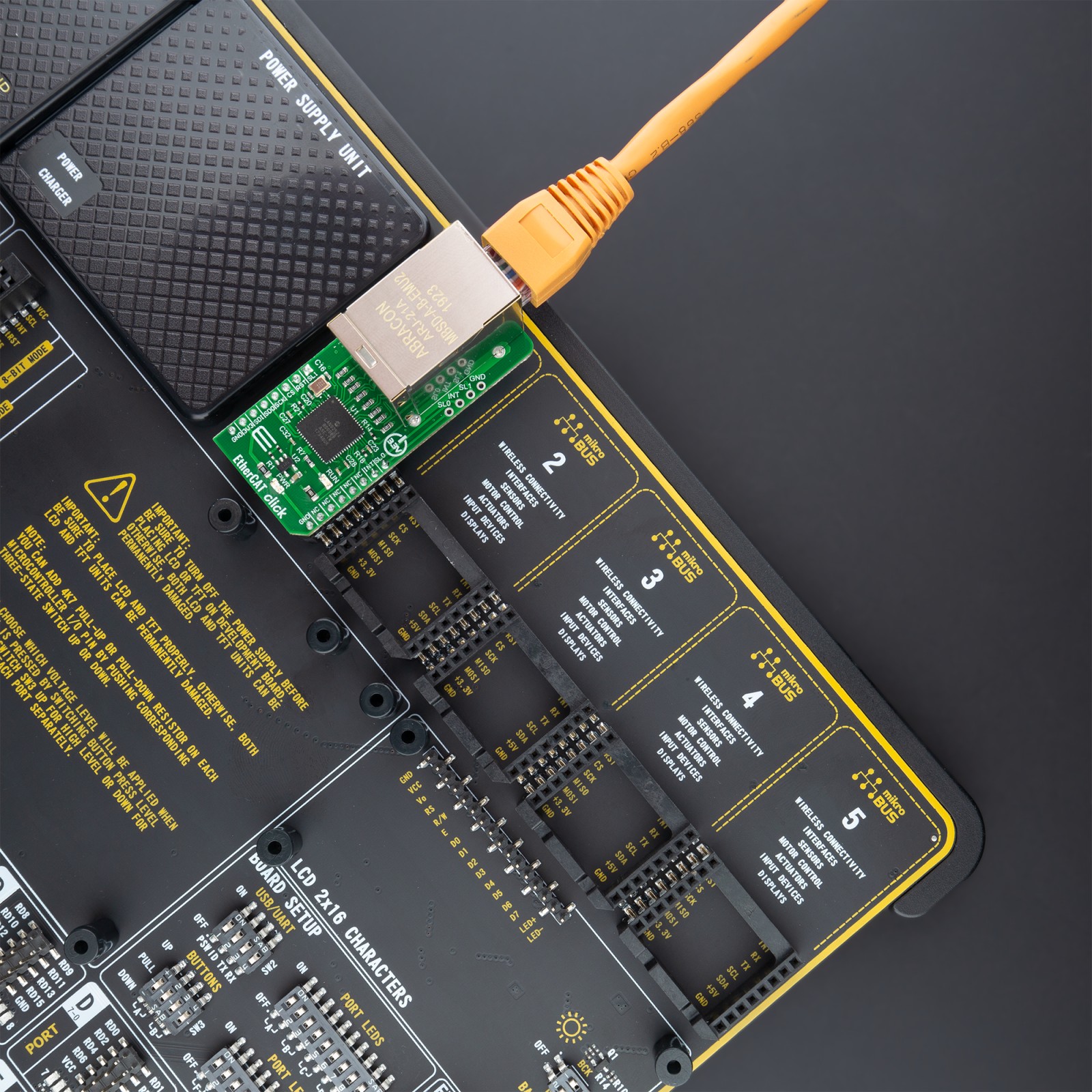
EtherCAT Click as its foundation uses the LAN9252, a 2-port EtherCAT device controller with dual integrated Ethernet PHYs from Microchip Technology. Each PHY contains a full-duplex 100BASE-TX transceiver and supports 100Mbps operation. Each port receives an EtherCAT frame, performs frame checking, and forwards it to the next port. Data exchange between master and device applications is comparable to a dual-ported memory (process memory), enhanced by special functions for consistency checking and data mapping (FMMU). The LAN9252 also supports HP Auto-MDIX, allowing the use of direct connects or cross-over LAN cables on the onboard 2×1 RJ-45 connector.

Within the LAN9252, two modes of operation are available: buffered or mailbox mode. In the buffered mode, both the local MCU and EtherCAT Master can write to the device concurrently. The buffer within the LAN9252 will always contain the latest data. If newer data arrives before a performed old data read, the old data will be dropped. In mailbox mode, buffer access by the local MCU and the EtherCAT Master is committed using handshakes, guaranteeing no data drop. The LAN9252 also contains an I2C master EEPROM controller for connection to the external 24FC64F, 64Kbit Microchip’s EEPROM, which allows for the storage and retrieval of static data using the I2C serial interface.
EtherCAT Click communicates with MCU via a synchronous slave SPI/SQI interface that facilitates communication between the device and a host system. It supports single/multiple registers read and write commands with incrementing, decrementing, and static addressing and allows access to the System CSRs, internal FIFOs, and memories. Single, Dual, and Quad bit lanes are supported in SPI mode with a clock rate of up to 80 MHz. For simple digital modules without MCUs, the LAN9252 can operate in Digital I/O Mode, where signals can be controlled or monitored by the EtherCAT Master.
The LAN9252 also provides operational green LED indicator labeled as RUN and a programmable interrupt structure controlled by the System Interrupt Controller. The interrupt pin labeled as INT on the mikroBUS™ socket can be configured as an open-drain output to facilitate the sharing of interrupts with other devices via onboard header. The programmable interrupt pin provides the user with the ability to optimize performance dependent upon the application requirements. Also, this Click board™ can reset through the Hardware Reset pin, labeled as RST on the mikroBUS™ socket.
The EtherCAT Core of the LAN9252 provides two input pins used for time stamping of external events, where both rising and falling edge time stamps are recorded. These pins are shared with the SL0 and SL1 pins on the mikroBUS™ socket and onboard header, respectively, to indicate the occurrence of time events. The LAN9252 supports numerous power management and Wake-Up features. It can be placed in a reduced power mode and be programmed to issue an external wake signal ideal for triggering system Power-Up using remote Ethernet Wake-Up events.
This Click board™ operates only with a 3.3V logic voltage level. The board must perform appropriate logic voltage level conversion before use with MCUs with different logic levels.
EtherCAT Technology
EtherCAT is a high-performance, low-cost, easy to use Industrial Ethernet technology with a flexible topology. This real-time Industrial Ethernet technology was originally developed by Beckhoff Automation. The EtherCAT protocol which is disclosed in the IEC standard IEC61158 is suitable for hard and soft real-time requirements in automation technology, in test and measurement and many other applications.
EtherCAT is also an open technology: anyone is allowed to implement or use it. MikroElektornika is from 2018 a proud member of the EtherCAT Technology Group. To find out more about this technology and how it can be used feel free to visit EtherCAT Technology page.
Specifications
Type
Ethernet
Applications
Can be used for industrial control, process/factory automation, hydraulic and pneumatic valve systems, power, and many more.
On-board modules
LAN9252 – 2-port EtherCAT slave controller with dual integrated Ethernet PHYs from Microchip Technology
Key Features
2/3-port EtherCAT slave controller, integrated Ethernet PHYs with HP Auto-MDIX, wake on LAN (WoL) support, high performance, synchronous slave SPI/SQI interface, and more.
Interface
SPI
Feature
No ClickID
Compatibility
mikroBUS™
Click board size
L (57.15 x 25.4 mm)
Input Voltage
3.3V
Pinout diagram
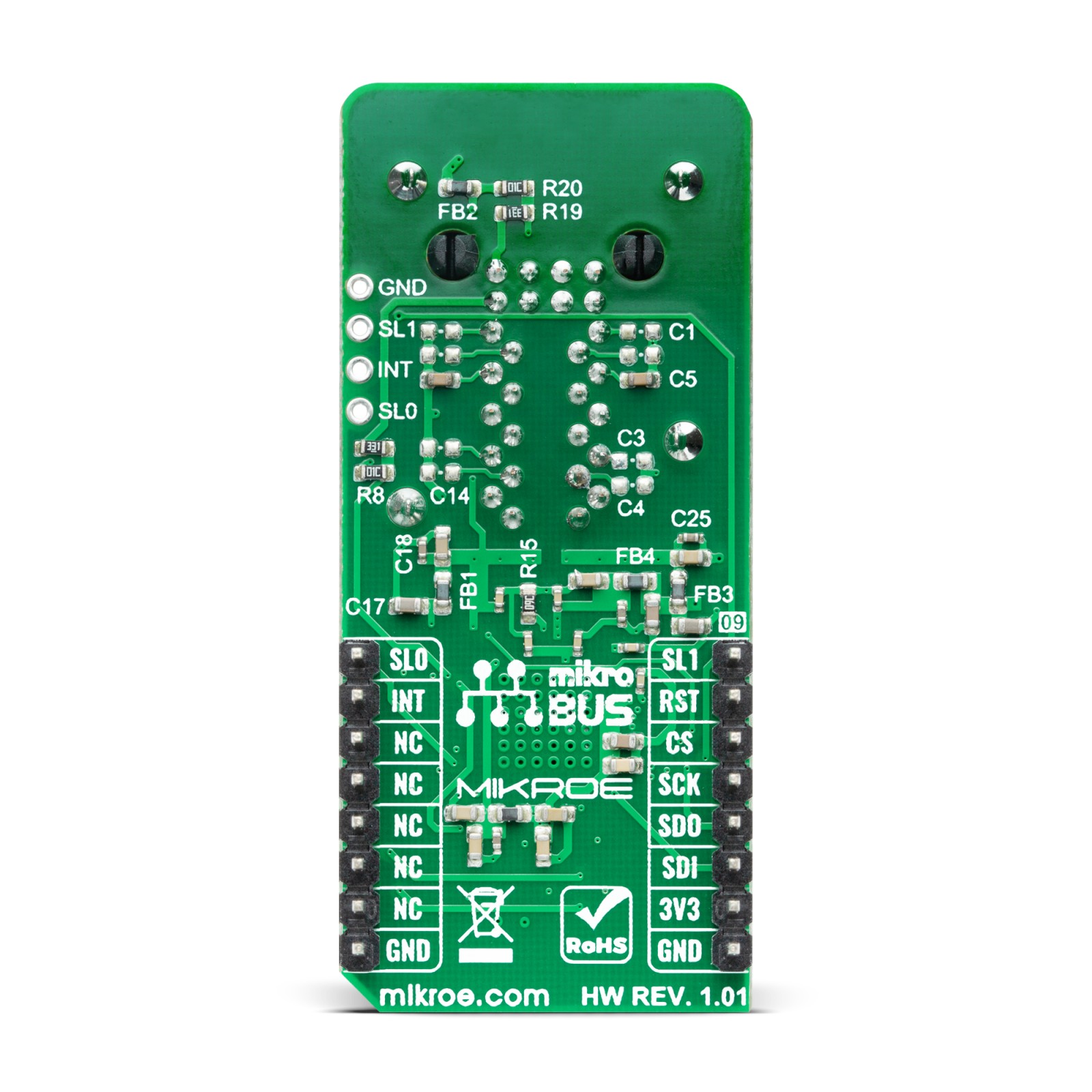
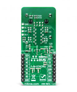
This table shows how the pinout on EtherCAT Click corresponds to the pinout on the mikroBUS™ socket (the latter shown in the two middle columns).
Onboard settings and indicators
| Label | Name | Default | Description |
|---|---|---|---|
| LD1 | PWR | – | Power LED Indicator |
| LD2 | RUN | – | RUN LED Indicator |
| J1 | – | Unpopulated | External Time Event Indicators / Interrupt |
EtherCAT Click electrical specifications
| Description | Min | Typ | Max | Unit |
|---|---|---|---|---|
| Supply Voltage | – | 3.3 | – | V |
| Bandwidth | – | 100BASE-TX/100BASE-FX | – | |
| Operating Temperature Range | -40 | +25 | +85 | °C |
Software support
MikroElektronika does not provide software support for this Click board™ in the form of libraries, functions, or example code at this moment. The software support is provided in MPLABX by the Microchip company, with Microchip EtherCAT Harmony 3 Driver.
Microchip Harmony 3 Driver can be found on the MicrochipTech GitHub account and represents the EtherCAT software development kit designed to be integrated into any suitably powerful MCU and is used to control LAN9252. Please refer to the LAN9252 Quick Start Guide for a quick getting up and running with EtherCAT Harmony 3 Driver.
For Technical support questions, the customers can submit a support case to Microchip by following the procedure in this link.
Resources
Downloads
| Weight | 35 g |
|---|---|
| Brand | MikroElektronika |

