How does it work?
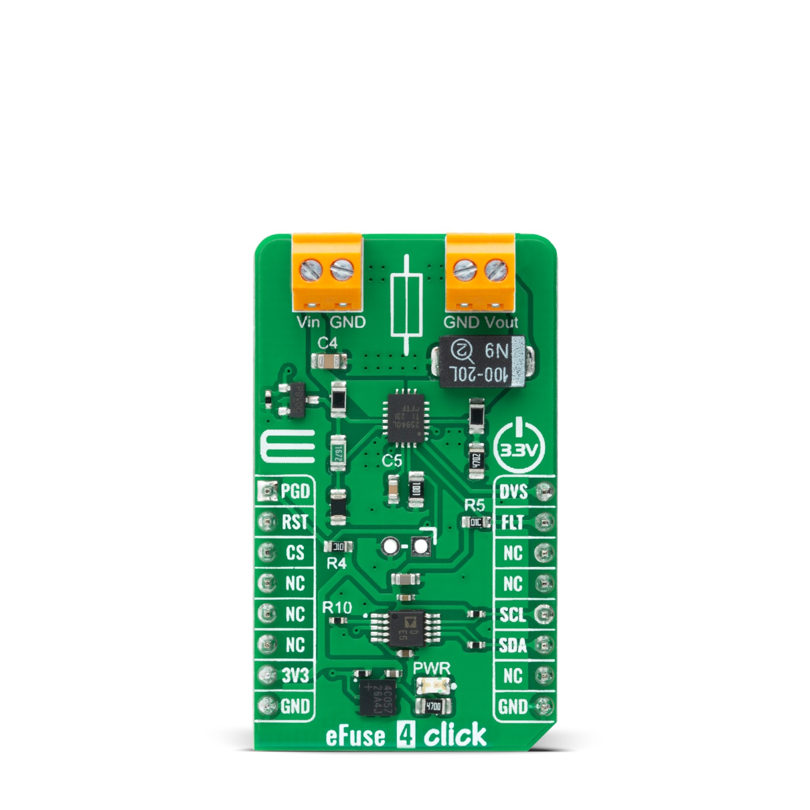
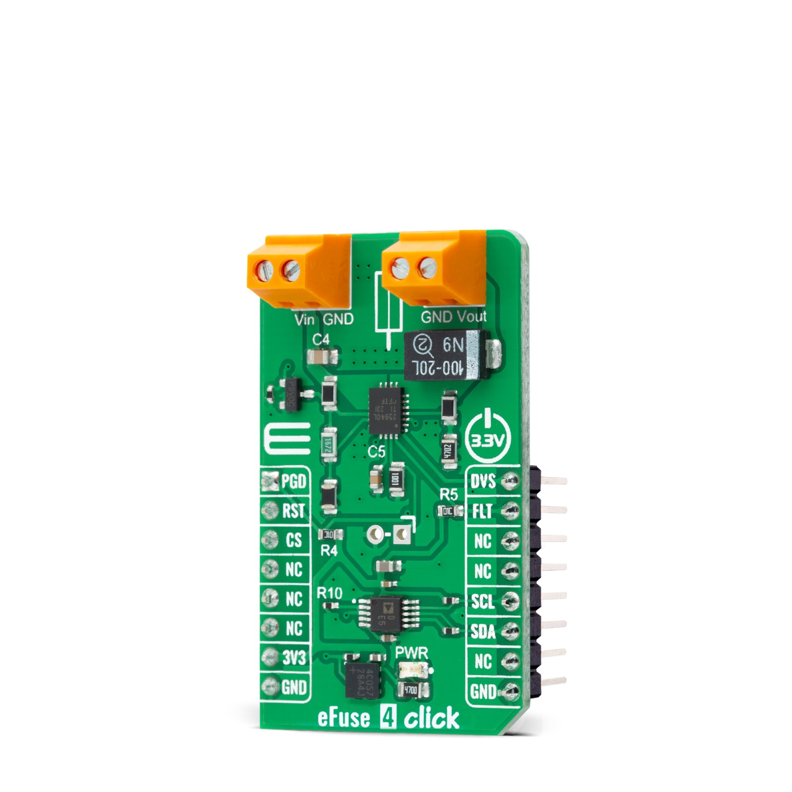
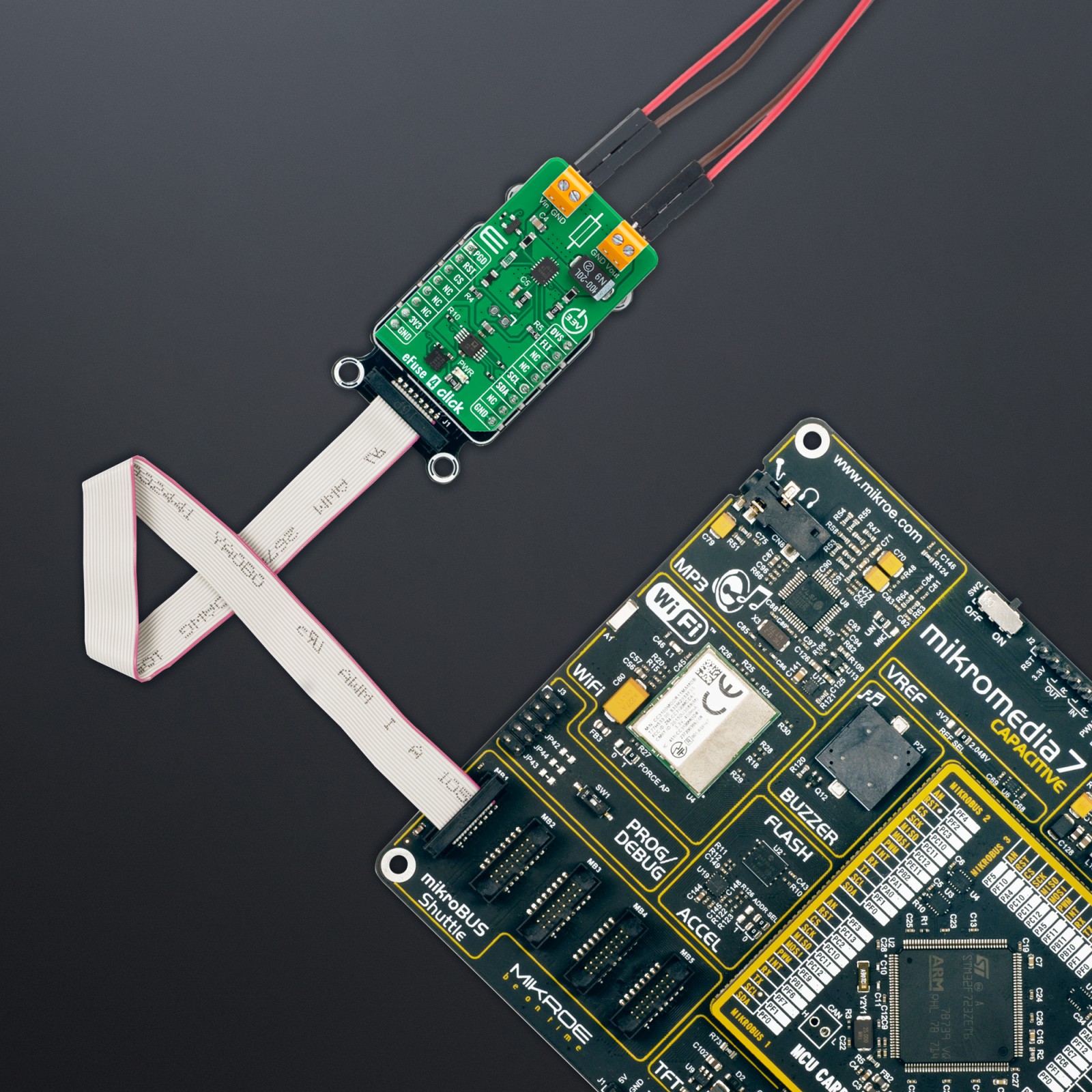
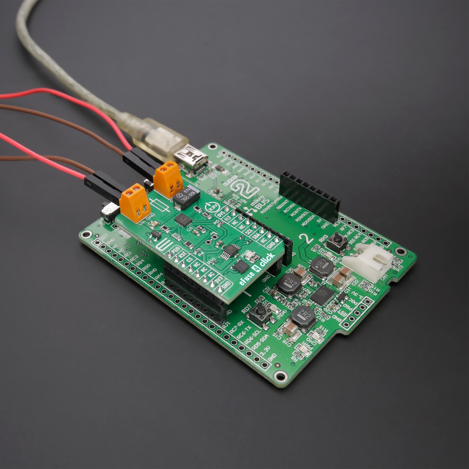
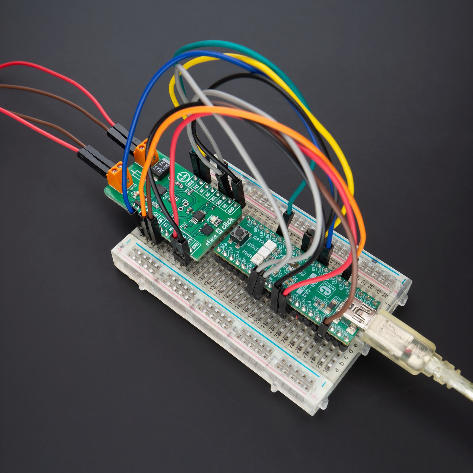
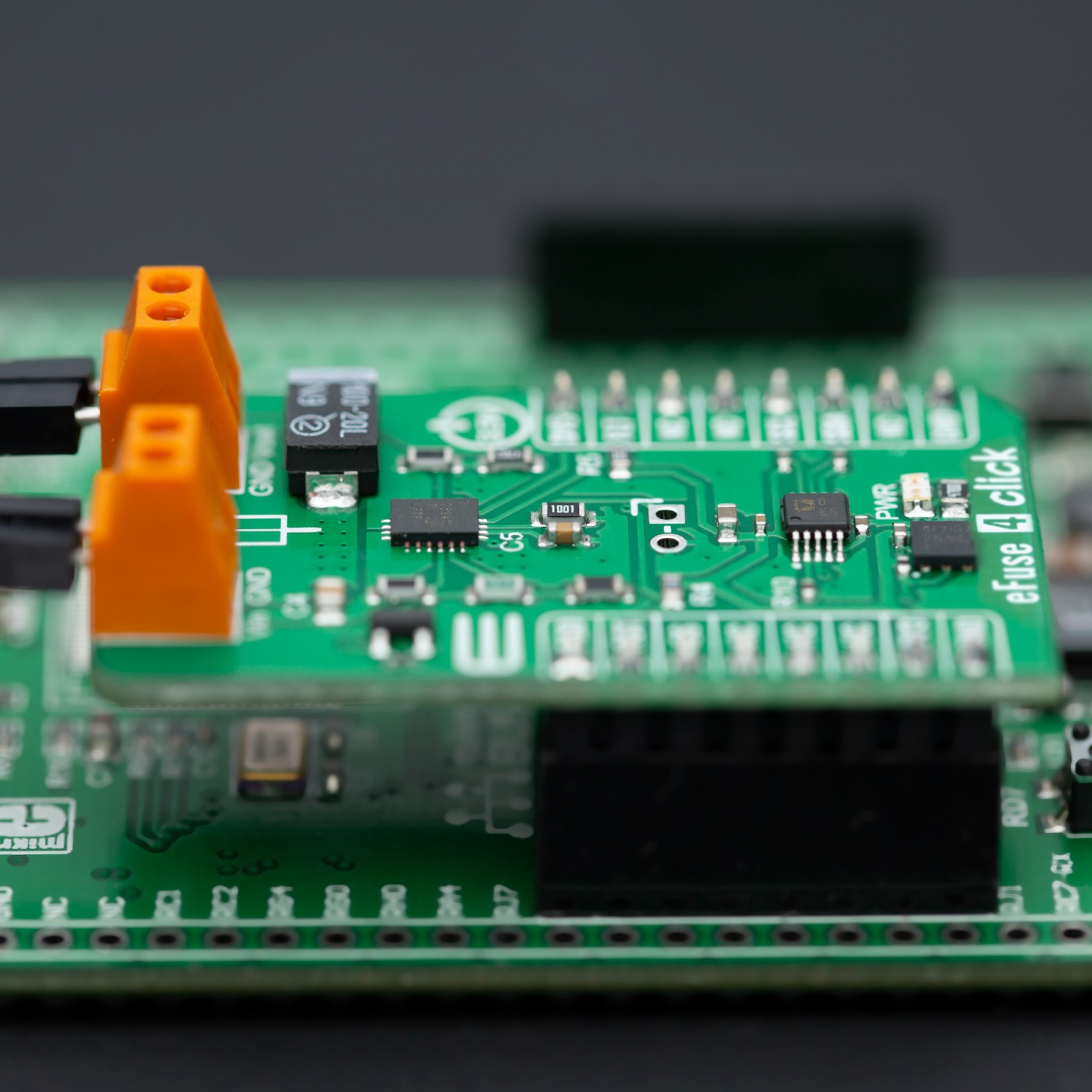
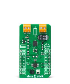
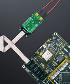
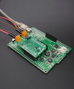
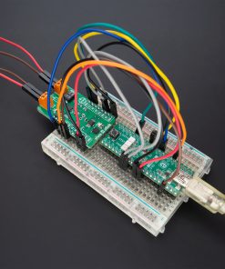
eFuse 4 Click is based on the TPS25940, a smart eFuse with integrated back-to-back FETs and enhanced built-in protection circuitry from Texas Instruments. The TPS25940 provides robust protection for all systems and applications powered by an external power supply from 2.7V to 18V. It also features a full suite of protection and monitoring functions, including a low-power DevSleep™ mode, controllable through a DVS pin routed on the PWM pin of the mikroBUS™ socket, that supports compliance with the SATA™ Device Sleep standard.
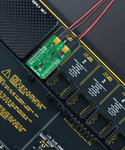
This Click board™ is designed to protect systems such as enterprise SSD drives against sudden power loss events. It monitors voltages of the input and output terminals to provide true reverse blocking from the output when a reverse condition or input power fail condition is detected. The TPS25940 allows users to program the overcurrent limit threshold between 1A and 5A via an external I2C-configurable digital potentiometer, the AD5272 from Analog Devices. Besides the overcurrent feature, the TPS25940 is also equipped with programmable over and undervoltage thresholds for load, source and device protection.
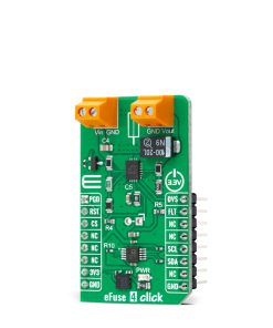
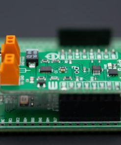
The TPS25940 also provides an additional power good comparator on the PGD pin, routed on the AN pin of the mikroBUS™ socket, with precision internal reference for output or any other rail voltage monitoring and a fault event indicator on the FLT pin. This fault indicator goes to a low logic state to indicate fault condition due to under/overvoltage, reverse voltage and thermal shutdown event in the event of an overcurrent. A special addition on the plate represents an unpopulated header which represents a precise current monitor output for health monitoring of the system, alongside Enable pin routed on the RST pin of the mikroBUS™ socket that controls the ON/OFF state of the internal TPS25940’s FETs.
This Click board™ can be operated only with a 3.3V logic voltage level. The board must perform appropriate logic voltage level conversion before using MCUs with different logic levels. However, the Click board™ comes equipped with a library containing functions and an example code that can be used as a reference for further development.
Specifications
Type
Power Switch
Applications
Can be used for systems with load-side holdup energy that must not drain back to a failed supply bus
On-board modules
TPS25940 – eFuse power switch from Texas Instruments
Key Features
Reverse current blocking, DevSleep support for SSDs, wide operating voltage, programmable current limit, current monitoring, protection features, power-good and fault indicators, and more
Interface
GPIO,I2C
Feature
ClickID
Compatibility
mikroBUS™
Click board size
M (42.9 x 25.4 mm)
Input Voltage
3.3V
Pinout diagram
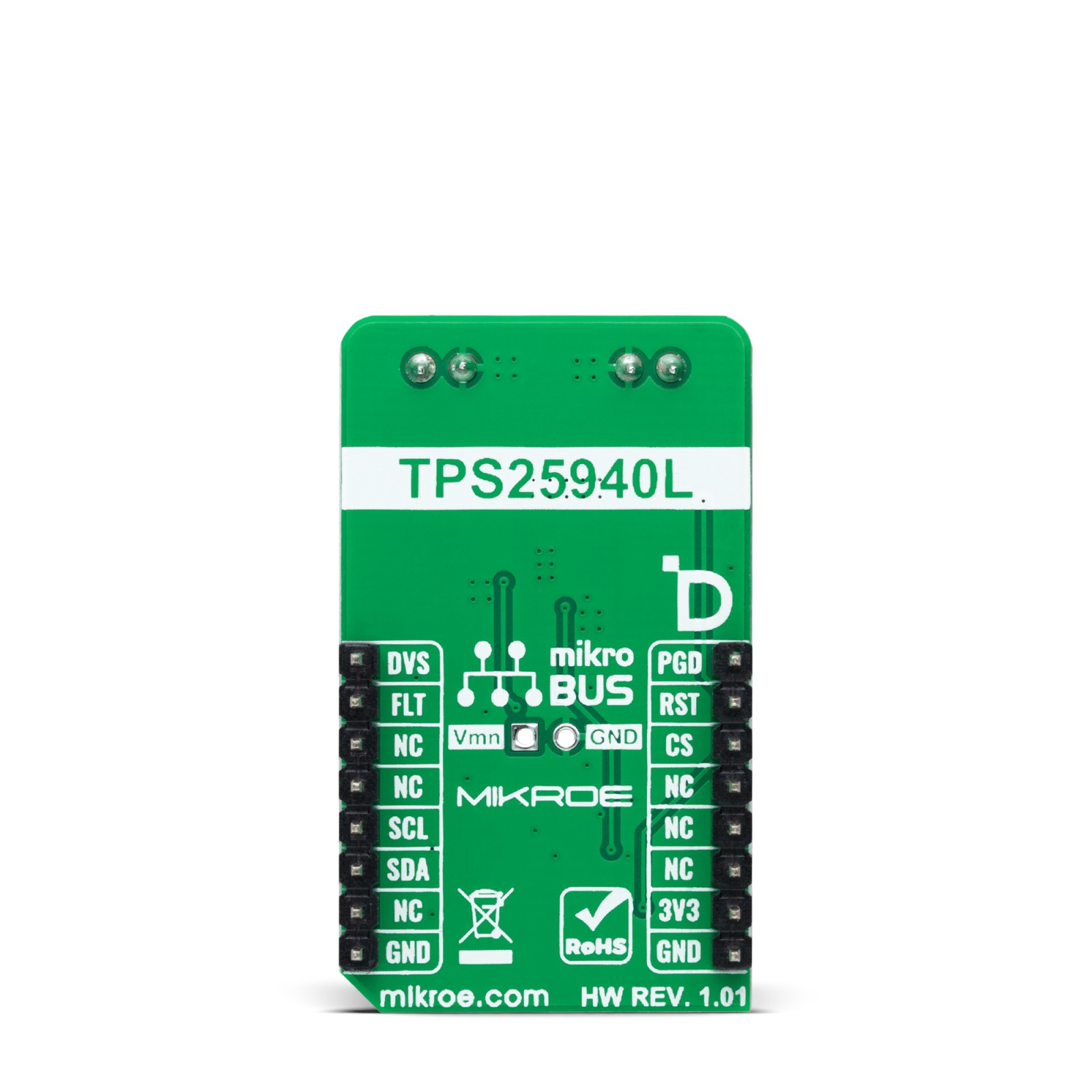
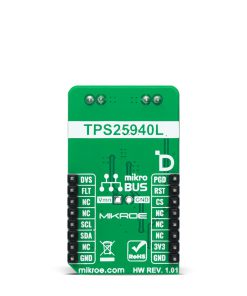
This table shows how the pinout on eFuse 4 Click corresponds to the pinout on the mikroBUS™ socket (the latter shown in the two middle columns).
Onboard settings and indicators
Label | Name | Default | Description |
---|---|---|---|
LD1 | PWR | – | Power LED Indicator |
J1 | – | Unpopulated | Current Monitor Header |
eFuse 4 Click electrical specifications
Description | Min | Typ | Max | Unit |
---|---|---|---|---|
Supply Voltage | – | 3.3 | – | V |
External Power Supply | 2.7 | – | 18 | V |
Output Current | 1 | – | 5 | A |
Software Support
We provide a library for the eFuse 4 Click as well as a demo application (example), developed using MikroElektronika compilers. The demo can run on all the main MikroElektronika development boards.
Package can be downloaded/installed directly from NECTO Studio Package Manager(recommended way), downloaded from our LibStock™ or found on Mikroe github account.
Library Description
This library contains API for eFuse 4 Click driver.
Key functions
-
efuse4_set_current_limit
eFuse 4 set current limit function. -
efuse4_set_resistance
eFuse 4 set resistance function. -
efuse4_set_digi_pot
eFuse 4 set normal mode function.
Example Description
This library contains API for the eFuse 4 Click driver. This driver provides the functions to set the current limiting conditions in order to provide the threshold of the fault conditions.
void application_task ( void )
{
static char index;
if ( EFUSE4_ERROR != log_read( &logger, &index, 1 ) )
{
if ( ( index >= '0' ) && ( index <= '6' ) )
{
efuse4_set_current_limit ( &efuse4, limit_value_op[ index - 48 ] );
log_printf( &logger, " >>> Selected mode %d rn", index - 48 );
log_printf( &logger, " Current limit is %d mA rn", limit_value_op[ index - 48 ] );
log_printf( &logger, "---------------------------rn" );
Delay_ms( 100 );
}
else
{
log_printf( &logger, " Data not in range! rn" );
log_printf( &logger, "---------------------------rn" );
display_selection( );
Delay_ms( 100 );
}
}
}
The full application code, and ready to use projects can be installed directly from NECTO Studio Package Manager(recommended way), downloaded from our LibStock™ or found on Mikroe github account.
Other Mikroe Libraries used in the example:
- MikroSDK.Board
- MikroSDK.Log
- Click.eFuse4
Additional notes and informations
Depending on the development board you are using, you may need USB UART click, USB UART 2 Click or RS232 Click to connect to your PC, for development systems with no UART to USB interface available on the board. UART terminal is available in all MikroElektronika compilers.
mikroSDK
This Click board™ is supported with mikroSDK – MikroElektronika Software Development Kit. To ensure proper operation of mikroSDK compliant Click board™ demo applications, mikroSDK should be downloaded from the LibStock and installed for the compiler you are using.
For more information about mikroSDK, visit the official page.