eFuse 3 Click
R440.00 ex. VAT
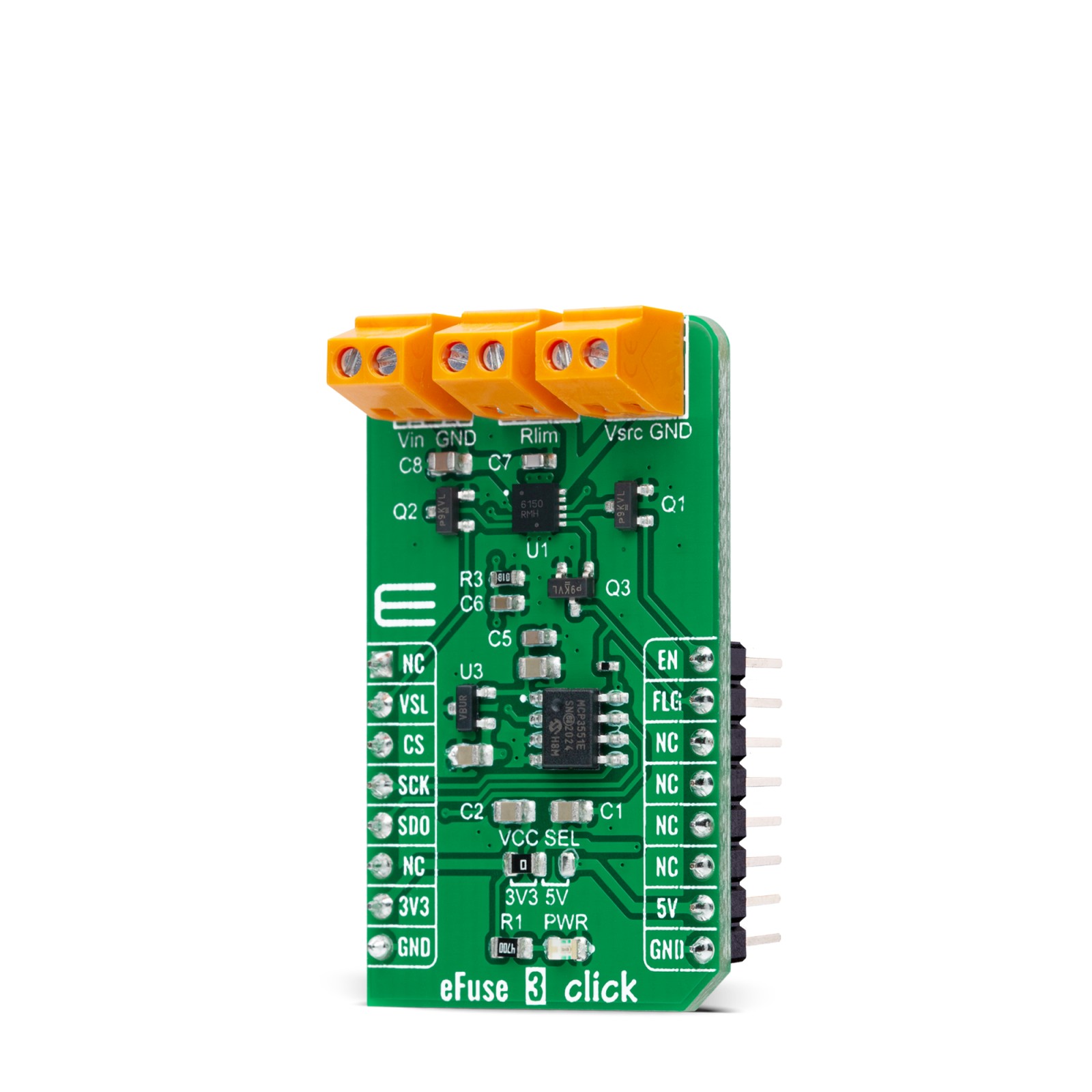
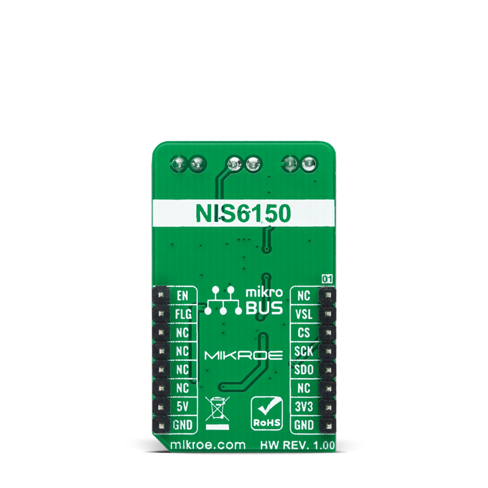
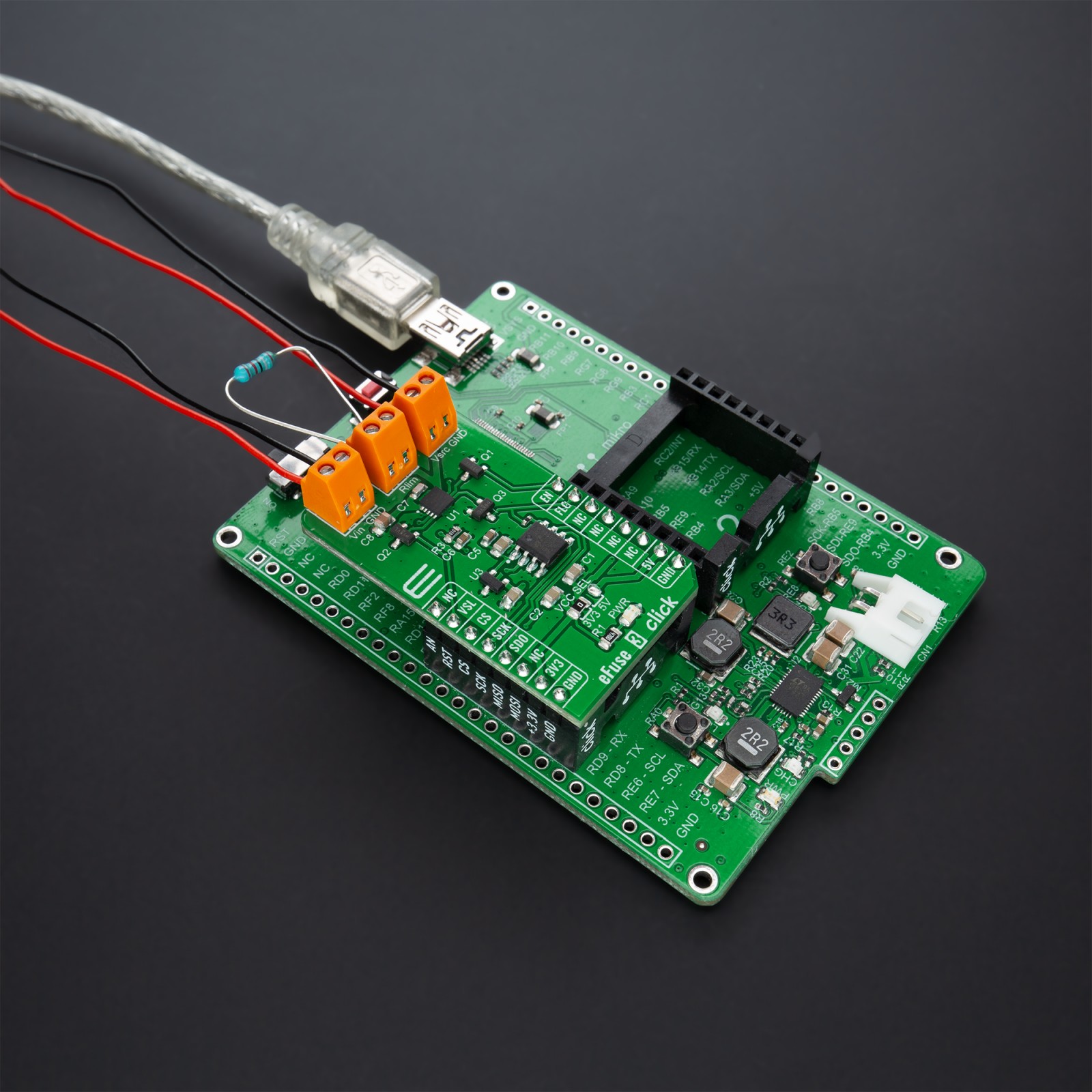
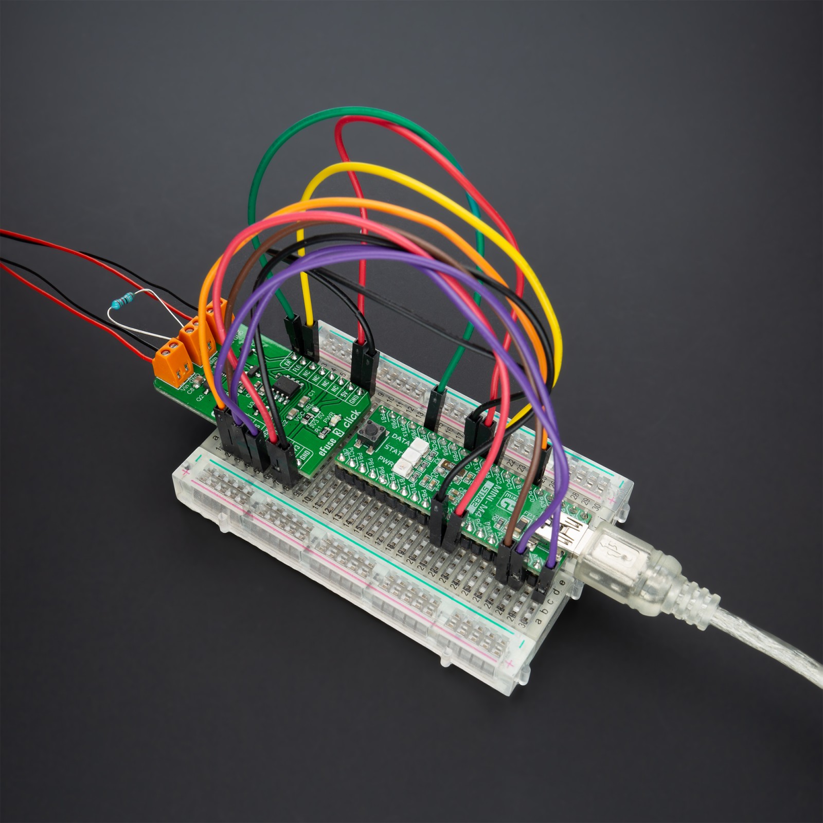
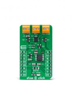
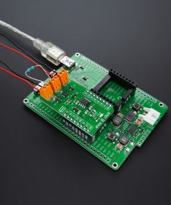
eFuse 3 Click is a compact add-on board that contains an electronic eFuse. This board features the NIS6150, a resettable fuse that can significantly enhance the reliability of a USB application from both catastrophic and shutdown failures from onsemi. It is designed to buffer the load device from the excessive input voltage, which can damage sensitive circuits and protect the input side from reverse currents. It includes an over-voltage clamp circuit that limits the output voltage during transients but doesn’t shut the unit down, allowing the load circuit to continue its operation. This Click board™ is suitable for automotive infotainment, overcurrent surge protection, and robust resettable fault protection.
eFuse 3 Click is supported by a mikroSDK compliant library, which includes functions that simplify software development. This Click board™ comes as a fully tested product, ready to be used on a system equipped with the mikroBUS™ socket.
Stock: Lead-time applicable.
| 5+ | R418.00 |
| 10+ | R396.00 |
| 15+ | R374.00 |
| 20+ | R359.92 |
How does it work?
eFuse 3 Click, as its foundation, uses the NIS6150, a self-protected, resettable electronic fuse from onsemi that contains circuits to monitor the input voltage, output voltage, output current, and die temperature. It comes with ENABLE feature with a separate ‘flag’ for fault identification, adjustable output current-limit protection with a thermal shutdown, and a current monitoring pin. The NIS6150 also includes an internal temperature sensing circuit that senses the temperature on the die of the power FET. If the temperature reaches 175°C, the device will shut down and remove power from the load.
.jpg)
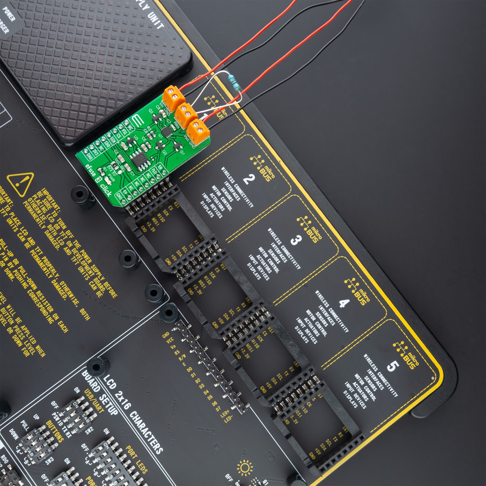
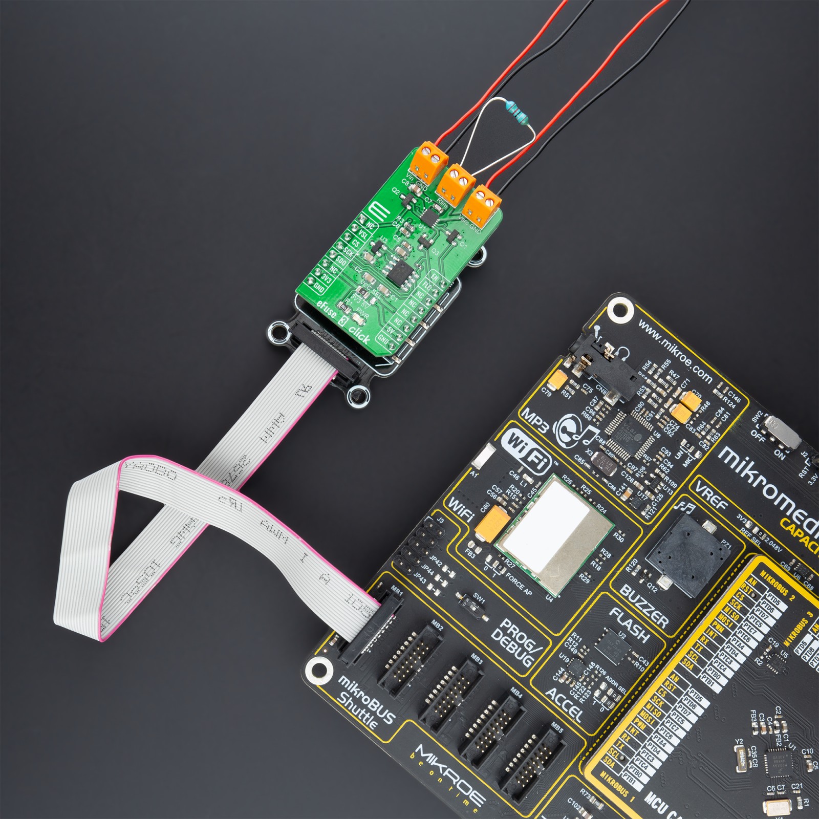
This Click board™ communicates with MCU through the 3-Wire SPI serial interface using the MCP3551, a 22bit sigma-delta ADC from Microchip. The MCP3551 is used for current monitoring purposes by converting the output current from NIS6150 IMON pin with a very high resolution of 22 bits and low noise to digital data, which can be obtained via the SPI interface of the Click board™. This ADC uses the reference voltage, the 4.096V reference voltage level provided by the MCP1541 from Microchip powered from the +5V mikroBUS™ power rail, resulting in high accuracy and stability. A resistor that connects to the middle connector on this Click board™, labeled as Rlim, sets the overload and short circuit current limit levels.
The VSL pin routed to the RST pin on the mikroBUS™ socket allows the overvoltage clamp to be set at either a 5.7 V or 6.5 V minimum by pulling this pin to a low logic state. It monitors the output voltage, and if the input exceeds the output voltage, the gate drive of the main FET is reduced to limit the output. This is intended to allow operation through transients while protecting the load. If an overvoltage condition exists for many seconds, the device may overheat due to the voltage drop across the FET combined with the load current. In this event, the thermal protection circuit would shut down the device.
The eFuse 3 Click also has active two additional pins of the mikroBUS™ socket, the INT and PWM pins labeled as FLG and EN. The Enable feature, routed to the PWM pin on the mikroBUS™ socket, provides a digital interface to control the output of the eFuse. That’s why when this pin is pulled to a low logic state – the eFuse is turned OFF. On the other hand, the ‘flag’ pin routed to the INT pin on the mikroBUS™ socket sends information to the MCU regarding the state of the chip. If a thermal fault occurs, the voltage on this pin will go to a low state to signal a monitoring circuit that the device is in thermal shutdown.
This Click board™ can operate with both 3.3V and 5V logic voltage levels selected via the VCC SEL jumper. This way, it is allowed for both 3.3V and 5V capable MCUs to properly use the SPI communication lines. However, the Click board™ comes equipped with a library containing easy-to-use functions and an example code that can be used, as a reference, for further development.
Specifications
Type
Power Switch
Applications
Can be used for automotive infotainment, overcurrent surge protection, and robust resettable fault protection.
On-board modules
NIS6150 – self-protected, resettable electronic fuse from onsemi
MCP3551 – 22bit sigma-delta ADC from Microchip
MCP1541 – 4.096V reference voltage from Microchip
Key Features
Integrated reverse current protection, adjustable current limit, current monitoring, increased efficiency, automotive qualified, and more.
Interface
SPI
Feature
No ClickID
Compatibility
mikroBUS™
Click board size
M (42.9 x 25.4 mm)
Input Voltage
3.3V or 5V
Pinout diagram
This table shows how the pinout on eFuse 3 Click corresponds to the pinout on the mikroBUS™ socket (the latter shown in the two middle columns).
Onboard settings and indicators
| Label | Name | Default | Description |
|---|---|---|---|
| LD1 | PWR | – | Power LED Indicator |
| JP1 | VCC SEL | – | Logic Level Voltage Selection 3V3/5V: Left position 3V3, Right position 5V |
eFuse 3 Click electrical specifications
| Description | Min | Typ | Max | Unit |
|---|---|---|---|---|
| Supply Voltage VCC | 3.3 | – | 5 | V |
| Supply Voltage VIN | – | 5 | 10 | V |
| Maximum Output Voltage | 5.7 | 6.1 | 6.7 | V |
| Current Limit | – | 1.2 | – | A |
| ON Resistance | – | 135 | 200 | mΩ |
| Operating Temperature Range | -40 | +25 | +150 | °C |
Software Support
We provide a library for the eFuse 3 Click as well as a demo application (example), developed using MikroElektronika compilers. The demo can run on all the main MikroElektronika development boards.
Package can be downloaded/installed directly from NECTO Studio Package Manager(recommended way), downloaded from our LibStock™ or found on mikroE github account.
Library Description
This library contains API for eFuse 3 Click driver.
Key functions:
efuse3_cfg_setup– Config Object Initialization function.efuse3_init– Initialization function.efuse3_default_cfg– Click Default Configuration function.
Examples description
This library contains API for the eFuse 3 Click driver. The library contains drivers to enable/disable the device, for reading ADC voltage, overflow status, output and current value [ A ].
The demo application is composed of two sections :
void application_task ( void ) {
log_printf( &logger, " Status :" );
if ( efuse3_get_flag( &efuse3 ) == EFUSE3_FLAG_NORMAL_OPERATION ) {
log_printf( &logger, " Normal operation rn" );
} else {
log_printf( &logger, " Device OFF rn" );
if ( overflow_status == EFUSE3_OVERFLOW_HIGH ) {
log_printf( &logger, " Overflow high in the analog input voltage.rn" );
} else if ( overflow_status == EFUSE3_OVERFLOW_LOW ) {
log_printf( &logger, " Overflow low in the analog input voltage.rn" );
}
efuse3_reset( &efuse3 );
Delay_ms( 1000 );
}
log_printf( &logger, "- - - - - - - - - - - - - - rn" );
efuse3_get_current( &efuse3, ¤t );
log_printf( &logger, " Current : %.5f Arn", current );
log_printf( &logger, "---------------------------rn" );
Delay_ms( 2000 );
}
The full application code, and ready to use projects can be installed directly from NECTO Studio Package Manager(recommended way), downloaded from our LibStock™ or found on mikroE github account.
Other mikroE Libraries used in the example:
- MikroSDK.Board
- MikroSDK.Log
- Click.eFuse3
Additional notes and informations
Depending on the development board you are using, you may need USB UART click, USB UART 2 click or RS232 click to connect to your PC, for development systems with no UART to USB interface available on the board. The terminal available in all MikroElektronika compilers, or any other terminal application of your choice, can be used to read the message.
mikroSDK
This Click board™ is supported with mikroSDK – MikroElektronika Software Development Kit. To ensure proper operation of mikroSDK compliant Click board™ demo applications, mikroSDK should be downloaded from the LibStock and installed for the compiler you are using.
For more information about mikroSDK, visit the official page.
Resources
Downloads
| Weight | 20 g |
|---|---|
| Brand | MikroElektronika |


