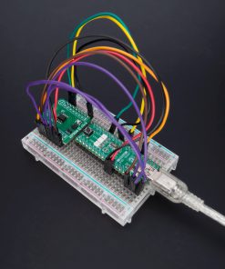
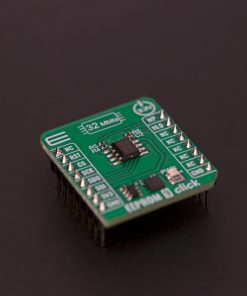
How does it work?
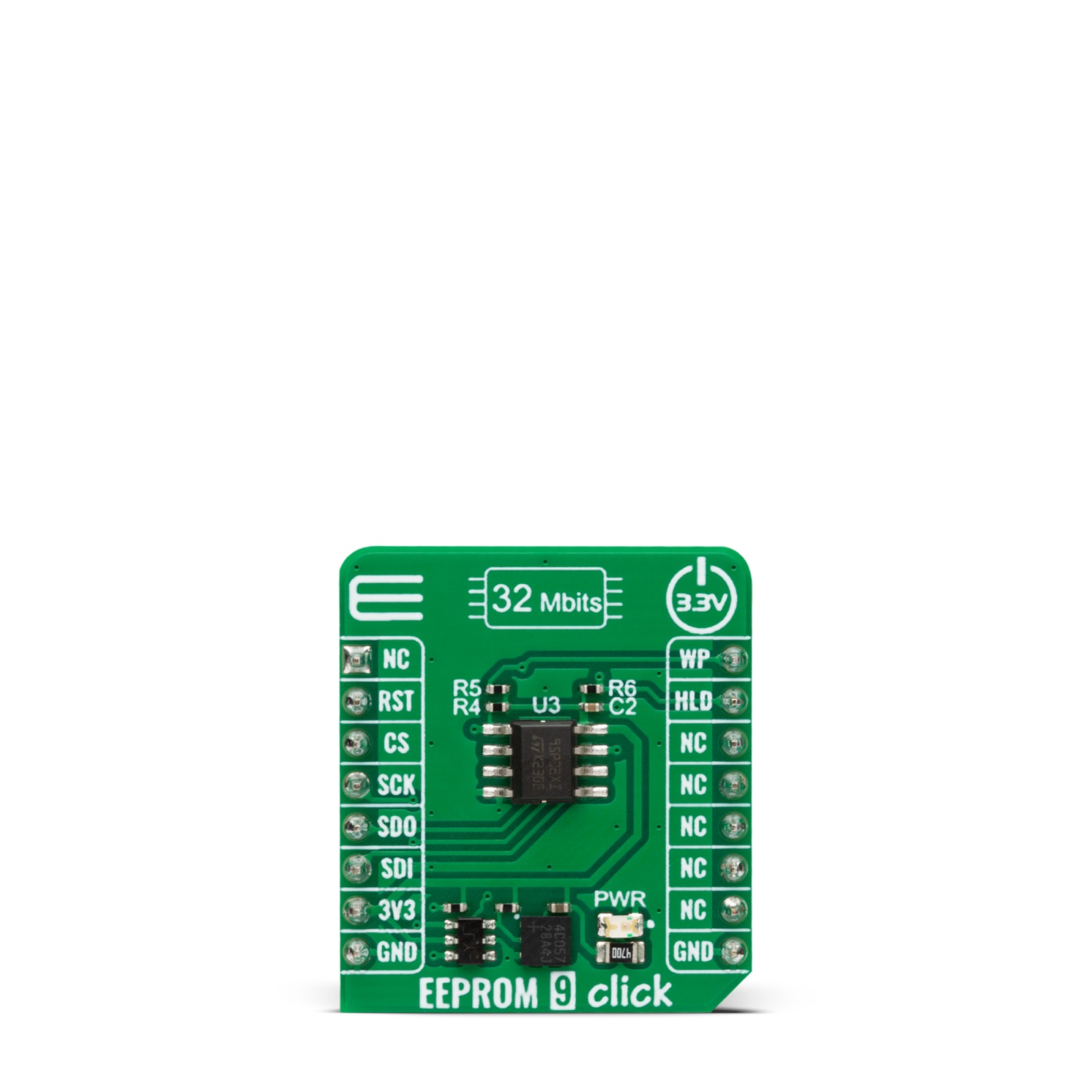
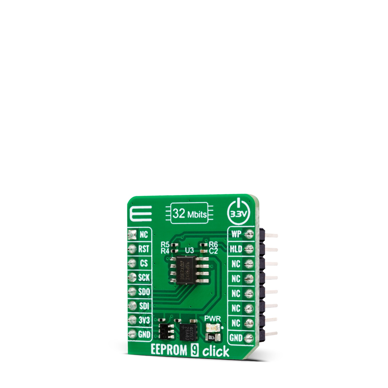
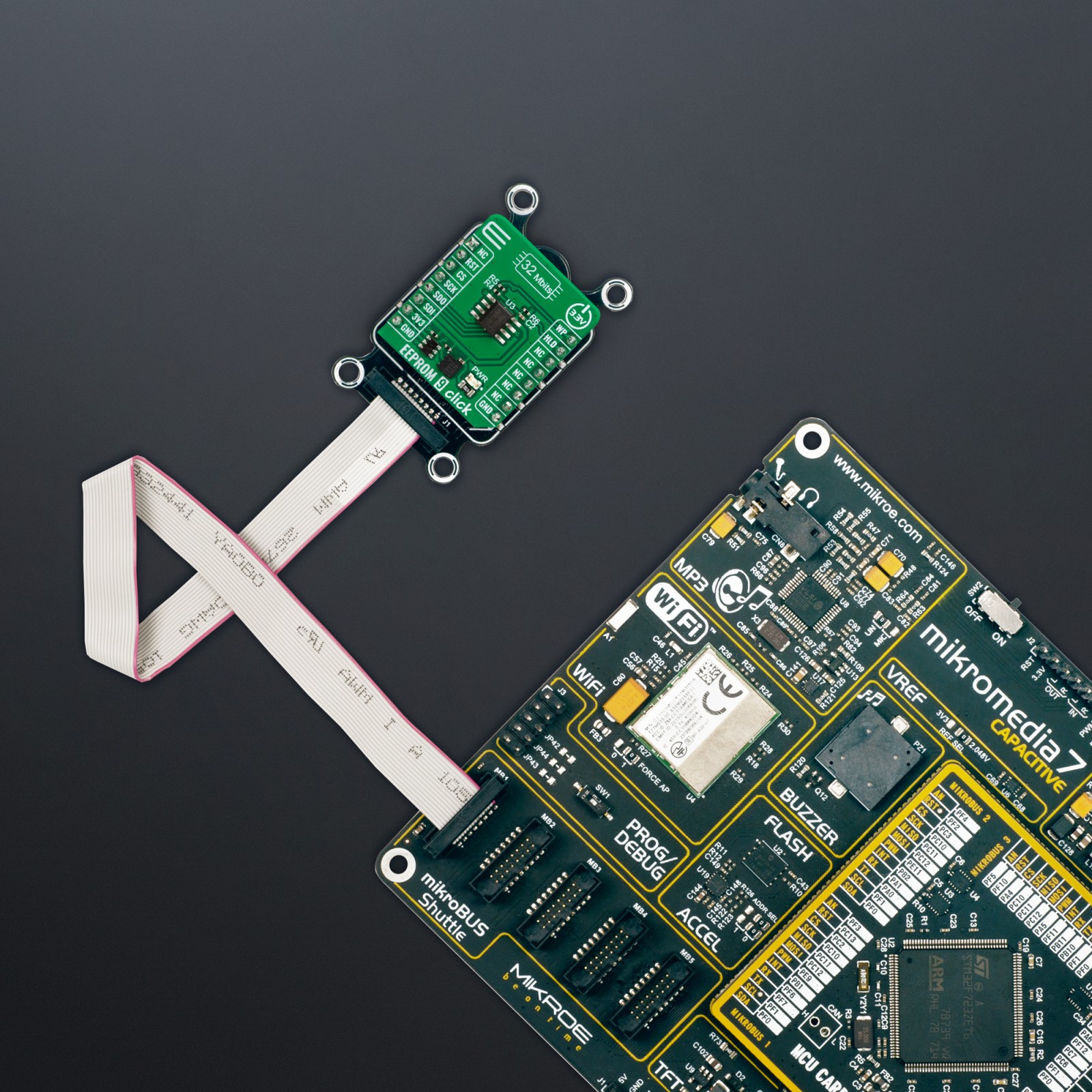
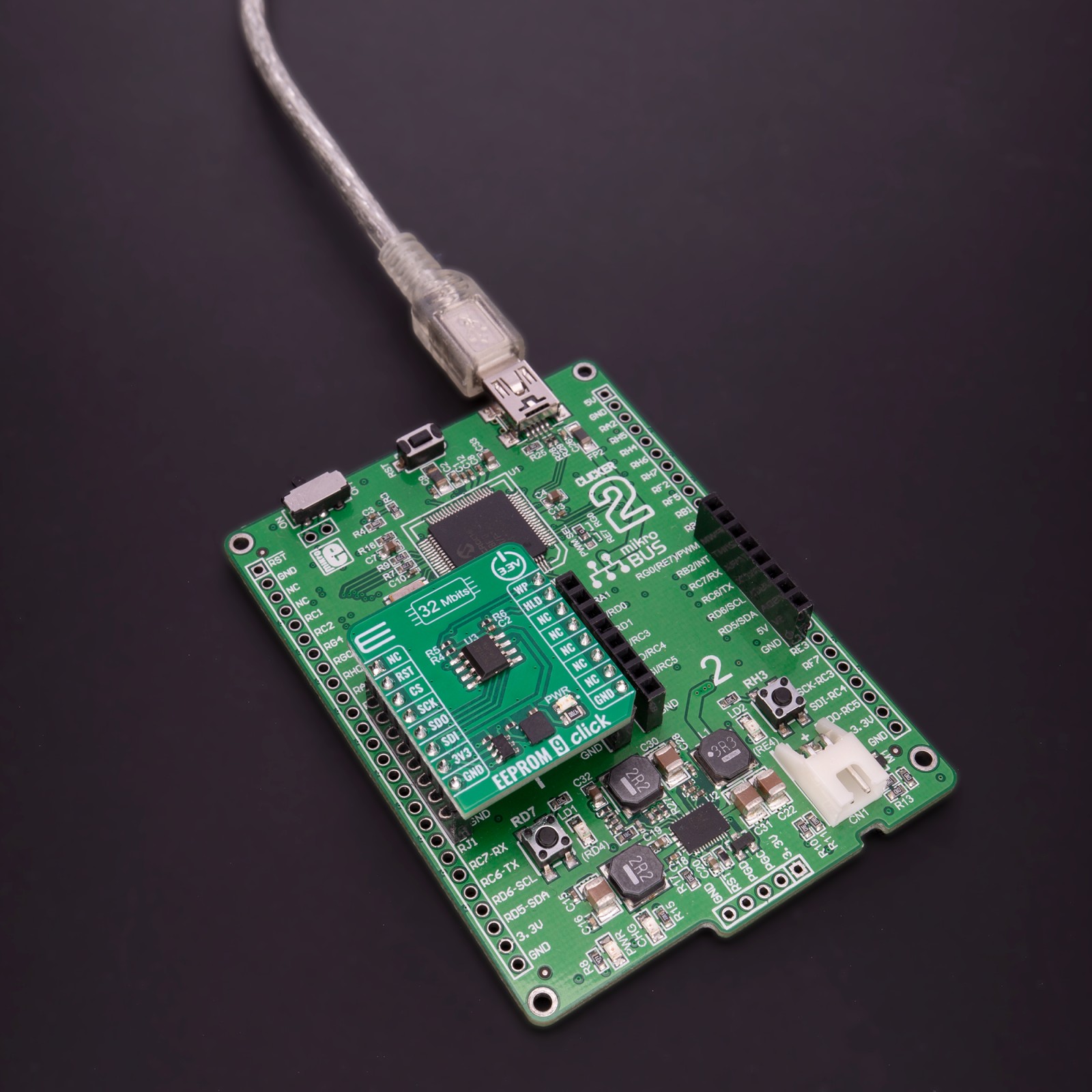
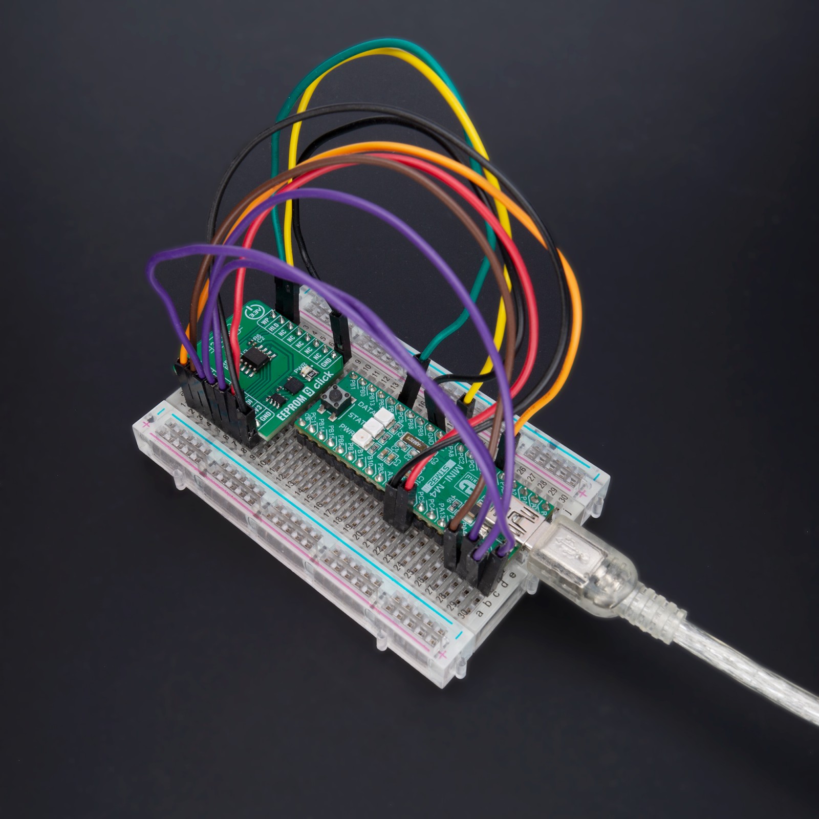
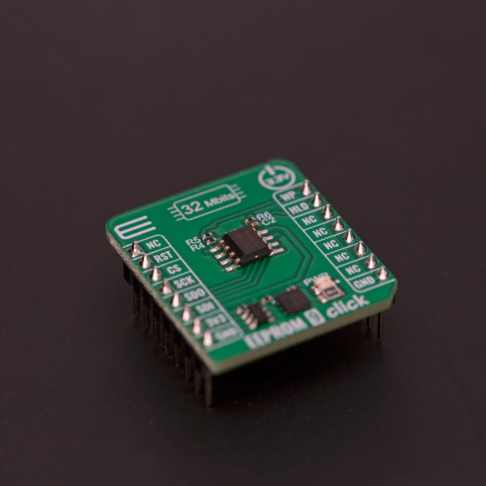
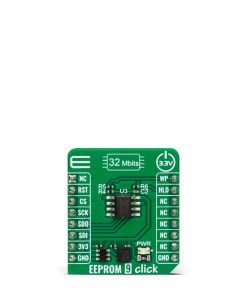
EEPROM 9 Click is based on the M95P32-I, a 32Mbit SPI page EEPROM device from STMicroelectronics, divided into 8192 erasable pages of 512 bytes (organized either as 1024 erasable sectors of 4 Kbytes, 64 erasable blocks of 64 Kbytes or as an entirely erasable array). The M95P32-I is manufactured with ST’s advanced proprietary NVM technology and offers byte flexibility, page alterability, high page cycling performance, and ultra-low power consumption. It is highly reliable, lasting 500k write cycles with 100 years of data retention (10 years after 500k cycles), which makes it suitable for various applications where dependable nonvolatile memory storage is essential.
This Click board™ communicates with MCU using the SPI serial interface that supports the two most common modes, SPI Mode 0 and 3, with a maximum SPI frequency of 80MHz. As mentioned, the M95P32-I offers byte and page write instructions of up to 512 bytes. Write instructions consist of self-timed auto-erase and program operations, resulting in flexible data byte management. It also accepts page/block/sector/chip erase commands to set the memory to an erased state. The memory can then be fast-programmed by pages of 512 bytes and further optimized using the “page program with buffer load” to hide the SPI communication latency. Additional status, configuration, and volatile registers set the desired device configuration, while the safety register gives device status information
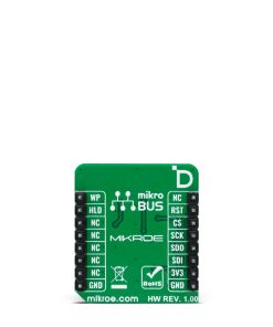
In addition to the SPI communication, the EEPROM 9 Click has two additional pins used for Write Protection and Communication Hold function routed to the WP and HLD pins of the mikroBUS™ socket. The HLD pin of the mikroBUS™ socket can be used to pause the serial communication with the M95P32-I without deselecting the device. The configurable Write Protection function routed to the WP pin of the mikroBUS™ socket allows the user to freeze the memory area protected against Write instructions in a read-only mode (as specified by the values in the BPx and TB bits of the STATUS register).
This Click board™ can only be operated with a 3.3V logic voltage level. The board must perform appropriate logic voltage level conversion before using MCUs with different logic levels. However, the Click board™ comes equipped with a library containing functions and an example code that can be used as a reference for further development.
Specifications
Type
EEPROM
Applications
Can be used for various consumer and industrial applications
On-board modules
M95P32-I – 32Mbit of page EEPROM from STMicroelectronics
Key Features
Fast read via SPI interface, ultra low power consumption, write endurance and data retention, high write/erase performance, write protection, communication hold function, and more
Interface
SPI
Feature
ClickID
Compatibility
mikroBUS™
Click board size
S (28.6 x 25.4 mm)
Input Voltage
3.3V
Pinout diagram
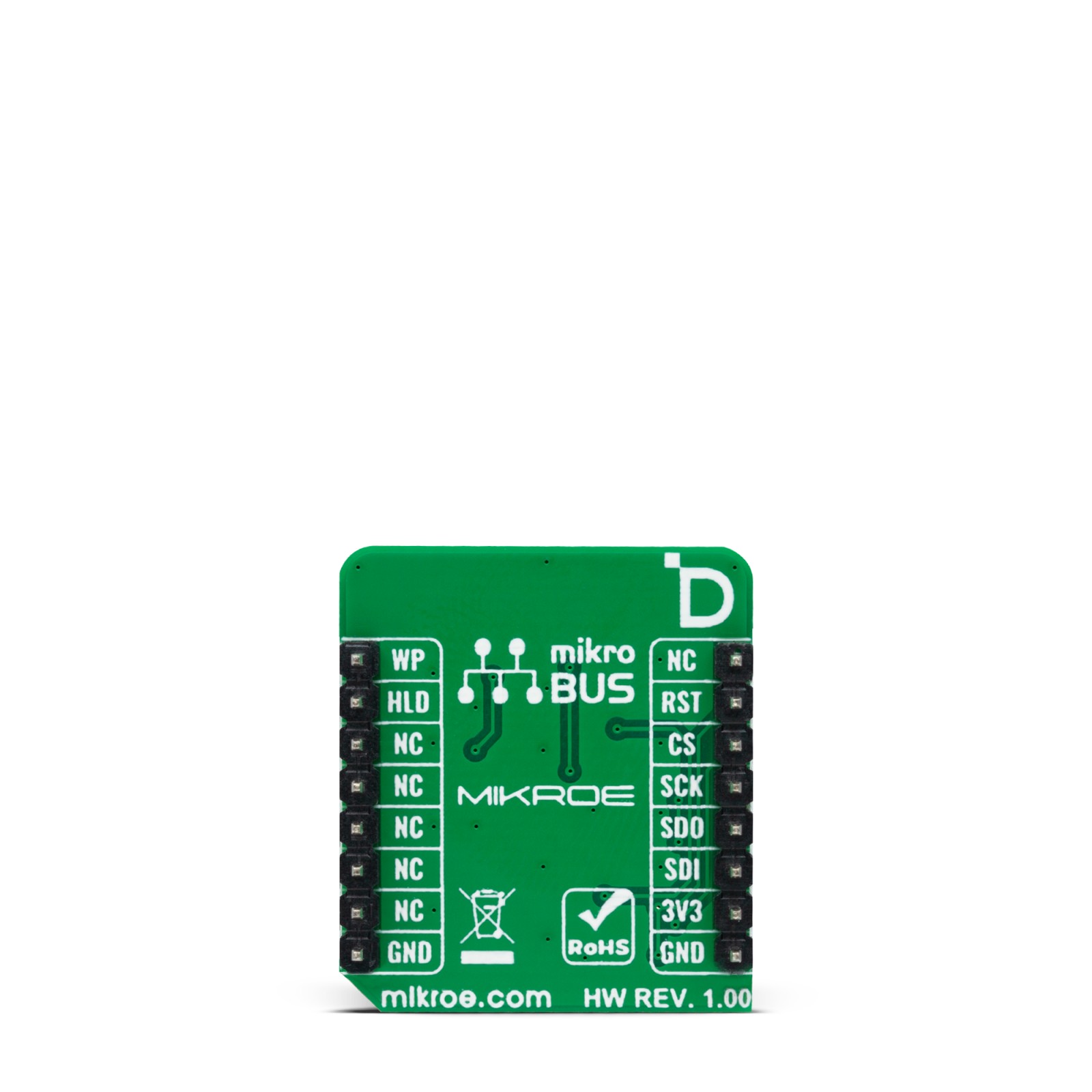
This table shows how the pinout on EEPROM 9 Click corresponds to the pinout on the mikroBUS™ socket (the latter shown in the two middle columns).
Onboard settings and indicators
Label | Name | Default | Description |
---|---|---|---|
LD1 | PWR | – | Power LED Indicator |
EEPROM 9 Click electrical specifications
Description | Min | Typ | Max | Unit |
---|---|---|---|---|
Supply Voltage | – | 3.3 | – | V |
Memory Size | – | – | 32 | Mbit |
Write Endurance | – | – | 50.000 | cycle |
Erase Endurance | – | – | 100 | cycle |
Software Support
We provide a library for the EEPROM 9 Click as well as a demo application (example), developed using Mikroe compilers. The demo can run on all the main Mikroe development boards.
Package can be downloaded/installed directly from NECTO Studio Package Manager (recommended), downloaded from our LibStock™ or found on Mikroe github account.
Library Description
This library contains API for EEPROM 9 Click driver.
Key functions
-
eeprom9_set_write_enable
EEPROM 9 enable write function. -
eeprom9_read_memory
EPROM 9 memory reading function. -
eeprom9_block_erase
EEPROM 9 memory block erase function.
Example Description
This is an example that demonstrates the use of the EEPROM 9 Click board™.
void application_task ( void )
{
char rx_data[ 9 ] = { 0 };
eeprom9_set_write_enable( &eeprom9, EEPROM9_WRITE_ENABLE );
Delay_ms( 10 );
eeprom9_write_memory( &eeprom9, MEMORY_ADDRESS, demo_data, 9 );
log_printf( &logger, " Write data: %s", demo_data );
Delay_ms( 100 );
eeprom9_read_memory( &eeprom9, MEMORY_ADDRESS, rx_data, 9 );
log_printf( &logger, " Read data: %s", rx_data );
log_printf( &logger, " - - - - - - - - - - - rn" );
Delay_ms( 1000 );
}
The full application code, and ready to use projects can be installed directly from NECTO Studio Package Manager (recommended), downloaded from our LibStock™ or found on Mikroe github account.
Other Mikroe Libraries used in the example:
- MikroSDK.Board
- MikroSDK.Log
- Click.EEPROM9
Additional notes and informations
Depending on the development board you are using, you may need USB UART click, USB UART 2 Click or RS232 Click to connect to your PC, for development systems with no UART to USB interface available on the board. UART terminal is available in all Mikroe compilers.
mikroSDK
This Click board™ is supported with mikroSDK – Mikroe Software Development Kit, that needs to be downloaded from the LibStock and installed for the compiler you are using to ensure proper operation of mikroSDK compliant Click board™ demo applications.
For more information about mikroSDK, visit the official page.