EEPROM 15 Click
R165.00 ex. VAT
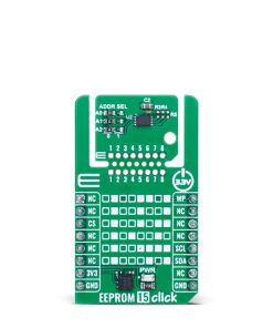
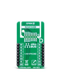
EEPROM 15 Click is a compact add-on board designed for reliable non-volatile data storage in embedded and computing systems. This board features the N34C04MU3ETG, a 4Kb serial EEPROM from onsemi, fully compliant with the JEDEC JC42.4 (EE1004−v) SPD specification for DDR4 DIMMs. This board supports I2C communication with selectable addresses and speeds up to 1MHz, includes a 16-byte page write buffer, and features a hardware Write Protect pin. Built on low-power CMOS technology, it offers 1 million write cycles and 100 years of data retention, ensuring long-term reliability. Thanks to MIKROE’s innovative Click Snap format, the board allows flexible implementation and standalone operation. It is ideal for applications in computing systems that require robust and efficient EEPROM storage.
EEPROM 15 Click is fully compatible with the mikroBUS™ socket and can be used on any host system supporting the mikroBUS™ standard. It comes with the mikroSDK open-source libraries, offering unparalleled flexibility for evaluation and customization. What sets this Click board™ apart is the groundbreaking ClickID feature, enabling your host system to seamlessly and automatically detect and identify this add-on board, alongside a Click Snap feature introducing a new level of flexibility and ease of use.
Stock: Lead-time applicable.
| 5+ | R156.75 |
| 10+ | R148.50 |
| 15+ | R140.25 |
| 20+ | R134.97 |
How does it work?
EEPROM 15 Click is based on the N34C04MU3ETG, a 4Kb serial EEPROM from onsemi, designed for reliable and efficient data storage in computing systems. It is specifically designed to meet the JEDEC JC42.4 (EE1004−v) Serial Presence Detect (SPD) specification for DDR4 DIMMs. This EEPROM supports multiple I2C communication modes, including Standard mode at 100kHz, Fast mode at 400kHz, and Fast Plus mode at up to 1MHz, making it versatile for various speed requirements in embedded applications. The N34C04MU3ETG version integrated on this board includes a unique response behavior where it issues a NoACK signal after receiving a dummy data byte, ensuring compatibility with SPD protocols. Additionally, it features a 16-byte page write buffer that enhances writing efficiency and minimizes the time needed for data programming. Based on a low-power CMOS technology, it offers an impressive endurance of up to one million write cycles and guarantees data retention for a minimum of 100 years, making it highly reliable for long-term applications, like use in computing environments that demand robust non-volatile memory with excellent performance and durability.

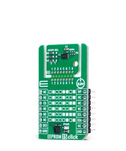
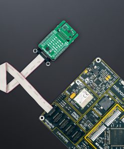
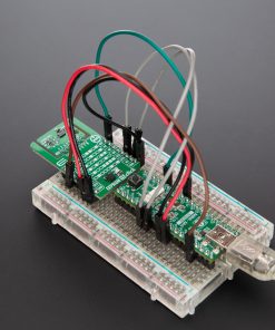
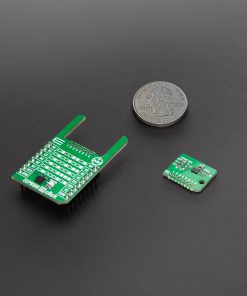
This Click board™ is designed in a unique format supporting the newly introduced MIKROE feature called “Click Snap.” Unlike the standardized version of Click boards, this feature allows the main IC area to become movable by breaking the PCB, opening up many new possibilities for implementation. Thanks to the Snap feature, the N34C04MU3ETG can operate autonomously by accessing its signals directly on the pins marked 1-8. Additionally, the Snap part includes a specified and fixed screw hole position, enabling users to secure the Snap board in their desired location.
As mentioned, this Click board™ uses an I2C interface with clock speeds of up to 1MHz, ensuring fast communication with the host MCU. The I2C address of the N34C04MU3ETG can be easily configured via onboard jumpers marked ADDR SEL in the Snap area, allowing multiple devices to coexist on the same bus. In addition to the I2C interface pins, EEPROM 15 Click features an WP pin used to inhibits all write operations, when pulled HIGH. One of the two available 2Kb EEPROM banks (referred to as SPD pages in the EE1004−v specification) is activated for access at power−up. After power−up, banks can be switched via software command. Each of the four 1Kb EEPROM blocks can be Write Protected by software command.
This Click board™ can be operated only with a 3.3V logic voltage level. The board must perform appropriate logic voltage level conversion before using MCUs with different logic levels. It also comes equipped with a library containing functions and example code that can be used as a reference for further development.
Click Snap
Click Snap is an innovative feature of our standardized Click add-on boards, introducing a new level of flexibility and ease of use. This feature allows for easy detachment of the main sensor area by simply snapping the PCB along designated lines, enabling various implementation possibilities. For detailed information about Click Snap, please visit the official page dedicated to this feature.
Specifications
Type
EEPROM
Applications
Ideal for applications in computing systems that require robust and efficient EEPROM storage
On-board modules
N34C04MU3ETG – 4Kb serial EEPROM from onsemi
Key Features
4Kb serial EEPROM, compliant with JEDEC JC42.4 (EE1004−v) SPD specification, supports I2C communication up to 1MHz, 16-byte page write buffer, low-power CMOS technology, 1 million write cycles endurance, 100 years data retention, unique NoACK response after dummy byte, dual-bank architecture with selectable SPD pages, Click Snap, and more
Interface
I2C
Feature
Click Snap,ClickID
Compatibility
mikroBUS™
Click board size
M (42.9 x 25.4 mm)
Input Voltage
3.3V
Pinout diagram
This table shows how the pinout on EEPROM 15 Click corresponds to the pinout on the mikroBUS™ socket (the latter shown in the two middle columns).
| Notes | Pin | Pin | Notes | ||||
|---|---|---|---|---|---|---|---|
| NC | 1 | AN | PWM | 16 | WP | Write Protect | |
| NC | 2 | RST | INT | 15 | NC | ||
| ID COMM | CS | 3 | CS | RX | 14 | NC | |
| NC | 4 | SCK | TX | 13 | NC | ||
| NC | 5 | MISO | SCL | 12 | SCL | I2C Clock | |
| NC | 6 | MOSI | SDA | 11 | SDA | I2C Data | |
| Power Supply | 3.3V | 7 | 3.3V | 5V | 10 | NC | |
| Ground | GND | 8 | GND | GND | 9 | GND | Ground |
Onboard settings and indicators
| Label | Name | Default | Description |
|---|---|---|---|
| LD1 | PWR | – | Power LED Indicator |
| JP1-JP3 | ADDR SEL | Left | I2C Address Selection 0/1: Left position 0, Right position 1 |
EEPROM 15 Click electrical specifications
| Description | Min | Typ | Max | Unit |
|---|---|---|---|---|
| Supply Voltage | – | 3.3 | – | V |
| Memory Size | – | – | 4 | Kb |
| Write Endurance | 1M | – | – | Cycles |
| Data Retention | 100 | – | – | Years |
Software Support
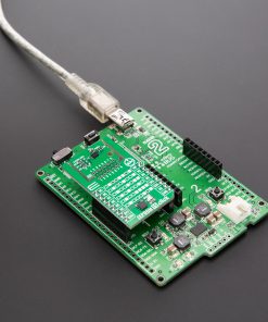
EEPROM 15 Click demo application is developed using the NECTO Studio, ensuring compatibility with mikroSDK‘s open-source libraries and tools. Designed for plug-and-play implementation and testing, the demo is fully compatible with all development, starter, and mikromedia boards featuring a mikroBUS™ socket.
Example Description
This example demonstrates the use of EEPROM 15 Click board by writing specified data to the memory and reading it back.
Key Functions
eeprom15_cfg_setupThis function initializes Click configuration structure to initial values.eeprom15_initThis function initializes all necessary pins and peripherals used for this Click board.eeprom15_select_bankThis function selects the active memory bank in the EEPROM.eeprom15_write_memoryThis function writes data to the EEPROM memory starting from the specified address.eeprom15_read_memoryThis function reads data from the EEPROM memory starting from the specified address.
Application Init
Initializes the driver and logger.
Application Task
Writes a desired number of bytes to the memory and then verifies if it is written correctly by reading from the same memory location and displaying the memory content on the USB UART.
Application Output
This Click board can be interfaced and monitored in two ways:
- Application Output – Use the “Application Output” window in Debug mode for real-time data monitoring. Set it up properly by following this tutorial.
- UART Terminal – Monitor data via the UART Terminal using a USB to UART converter. For detailed instructions, check out this tutorial.
Additional Notes and Information
The complete application code and a ready-to-use project are available through the NECTO Studio Package Manager for direct installation in the NECTO Studio. The application code can also be found on the MIKROE GitHub account.
Resources
Downloads
| Weight | 17 g |
|---|---|
| Brand | MikroElektronika |