EEG Click
R995.00 ex. VAT
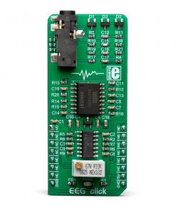
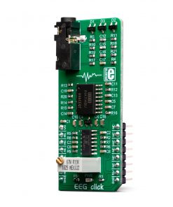
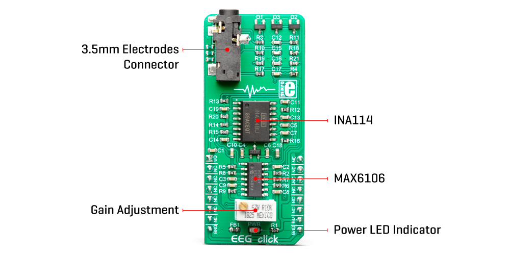
EEG Click is a Click board™ that allows monitoring of brain activity. Although not suitable for clinical examination, it is quite sufficient to allow some insight into brain activity. EEG click is equipped with a high-sensitivity circuit which amplifies faint electrical signals from the brain, allowing them to be sampled by a host MCU. To allow sufficiently high gain with no interferences, EEG click uses the INA114, a precision instrumentation amplifier, LASER trimmed for very low offset voltage, featuring very good common mode rejection ratio. This Click board™ can be used with the set of silver-chloride electrodes.
EEG click is supported by a mikroSDK compliant library, which includes functions that simplify software development. This Click board™ comes as a fully tested product, ready to be used on a system equipped with the mikroBUS™ socket.
Stock: Lead-time applicable.
| 5+ | R945.25 |
| 10+ | R895.50 |
| 15+ | R845.75 |
| 20+ | R813.91 |
Monitoring brain activity gains its popularity lately, as due to the fact that many commercially available integrated circuits emerge on market, almost daily. High-performance instrumentation amplifier ICs are affordable, making applications such as EEG click possible. EEG training, a technique of mental training method which makes the trainee consciously aware of the general activity in the brain is one of the applications where EEG click can be very useful. It can be also used for experimentation and development of brain-machine interface applications, or for simple monitoring of the brain activity.
What is EEG?
Electroencephalography is a method used to record the electrical activity of the brain. This is a non-invasive method which uses a number of electrodes placed along the scalp. EEG measures voltage fluctuations which appear as a result of the ionic currents within the neurons of the brain. The measurement can be focused either on event-related potential changes (ERP) or on spectral content of the signal, collected during a certain period. EEG is most often used to diagnose epilepsy, which causes abnormal changes of EEG readings.
How does it work?
EEG click is a single channel EEG monitoring device, based on the INA114, a precision instrumentation amplifier (IA) by Burr Brown®, a division of Texas Instruments, specialized in high-performance analog and mixed signal ICs. This IC offers a very low noise, LASER trimmed offset voltage, and very good common-mode rejection ratio. It uses a single resistor to set up its gain, which can easily be set up to 10,000. On this Click board™, the INA114 IA has its gain set to about 12 times. Further amplification and signal filtering is done by the MCP609, a four-channel op-amp from Microchip, so that the final gain factor is about 7800 times. Such high amplification is necessary in order to amplify very faint voltages generated during the brain activity. To fine-tune the amplification, there is a multi-turn precision potentiometer which allows to set the gain of the intermediate amplification stage between 10 and 100 times.
Since the “brain waves ” can be both positive and negative, EEG click uses a virtual GND at the potential of 2.048V. This also helps reducing the noise from the common GND, improving the readings quality. The amplified brain activity signal is available at the AN pin of the mikroBUS™, allowing sampling by the host MCU.
EEG measurements should be ideally conducted in an electrically isolated room, since any type of electromagnetic interference (EMI) could corrupt the measurement data. However, the INA114 offers some EMI protection, as it features an extremely good common-mode rejection ratio (CMRR), allowing to successfully cancel out most of induced interferences.
This Click board™ uses 3-electrode setup, which can be connected over a 3.5mm Jack connector on the Click board™. Although the best results can be achieved by using silver-chlorine plated electrodes, any type of electrodes can be used. EEG uses the DRL electrode placement scheme: two electrodes are placed behind the ears, while the third electrode is placed on the forehead. The DRL electrode (on the forehead) helps eliminating the common voltage, while two other electrodes are connected to the differential inputs of the INA114 IA.
The complete signal path is very well protected against voltage spikes and transients, that might appear as a result of the electrostatic discharge (ESD) in contact with the human body, so there is a set of ESD suppressing diodes and TVS diodes, which prevent sensitive IA and operational amplifiers on its output to become damaged by ESD events.
Specifications
Type
Biometrics
Applications
EEG click can be used in EEG biofeedback mental training, for experimentation and development of brain-machine interface applications, or for simple monitoring of the brain activity.
On-board modules
INA114, a precision instrumentation amplifier (IA) by Texas Instruments; MCP609, a four-channel operational amplifier from Microchip; MAX6106, a 2.048V reference from Maxim Integrated.
Key Features
ESD and EMI protection of the inputs, compatible with several types of electrodes, high-precision instrumentation amplifier with high CMRR, gain regulation, etc.
Interface
Analog
Feature
No ClickID
Compatibility
mikroBUS™
Click board size
L (57.15 x 25.4 mm)
Input Voltage
5V
Pinout diagram
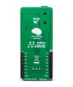
This table shows how the pinout on EEG Click corresponds to the pinout on the mikroBUS™ socket (the latter shown in the two middle columns).
| Notes | Pin | Pin | Notes | ||||
|---|---|---|---|---|---|---|---|
| EEG signal OUT | AN | 1 | AN | PWM | 16 | NC | |
| NC | 2 | RST | INT | 15 | NC | ||
| NC | 3 | CS | RX | 14 | NC | ||
| NC | 4 | SCK | TX | 13 | NC | ||
| NC | 5 | MISO | SCL | 12 | NC | ||
| NC | 6 | MOSI | SDA | 11 | NC | ||
| NC | 7 | 3.3V | 5V | 10 | 5V | Power Supply | |
| Ground | GND | 8 | GND | GND | 9 | GND | Ground |
Onboard settings and indicators
| Label | Name | Default | Description |
|---|---|---|---|
| PWR | PWR | – | Power LED indicator |
| CN1 | 3.5mm JACK | – | 3.5mm electrodes connector |
Software Support
We provide a library for the EEG Click as well as a demo application (example), developed using MIKROE compilers. The demo can run on all the main MIKROE development boards.
Package can be downloaded/installed directly from NECTO Studio Package Manager (recommended), downloaded from our LibStock™ or found on MIKROE github account.
Library Description
This library contains API for EEG Click driver.
Key functions
-
eeg_read_an_pin_valueThis function reads results of AD conversion of the AN pin. -
eeg_read_an_pin_voltageThis function reads results of AD conversion of the AN pin and converts them to proportional voltage level.
Example Description
This example demonstrates the use of EEG Click.
 void application_task ( void )
 {
     uint16_t eeg_an_value = 0;

     if ( eeg_read_an_pin_value( &eeg, &eeg_an_value ) != ADC_ERROR ) {
         log_printf( &logger, " %u,%lurn", eeg_an_value, time );
         Delay_ms ( 5 );
         time += 5;
     }
 }
The full application code, and ready to use projects can be installed directly from NECTO Studio Package Manager (recommended), downloaded from our LibStock™ or found on MIKROE github account.
Other MIKROE Libraries used in the example:
- MikroSDK.Board
- MikroSDK.Log
- Click.EEG
Additional notes and informations
Depending on the development board you are using, you may need USB UART click, USB UART 2 Click or RS232 Click to connect to your PC, for development systems with no UART to USB interface available on the board. UART terminal is available in all MIKROE compilers.
mikroSDK
This Click board™ is supported with mikroSDK – MIKROE Software Development Kit. To ensure proper operation of mikroSDK compliant Click board™ demo applications, mikroSDK should be downloaded from the LibStock and installed for the compiler you are using.
For more information about mikroSDK, visit the official page.
Resources
Downloads
| Weight | 22 g |
|---|---|
| Brand | MikroElektronika |