How does it work?
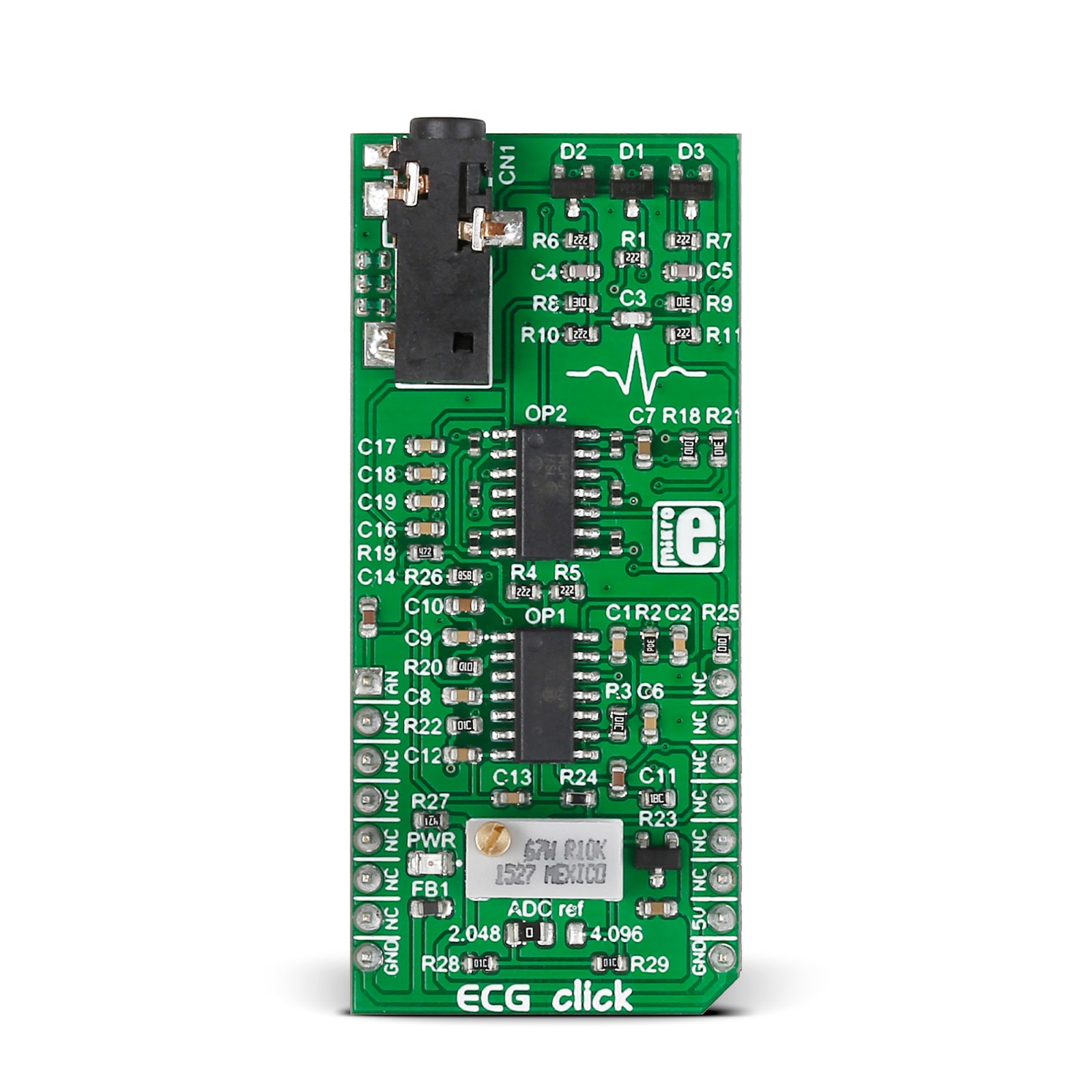
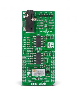
ECG Click is based on two MCP609s, a micropower CMOS operational amplifier from Microchip. These are unity-gain stable, rail-to-rail output swing operational amplifiers with a low offset voltage and input bias current designed to prevent phase reversal when the input pins exceed the supply voltages. ECG Click has a seven-block design. It comprises ESD, overvoltage and overcurrent protection (protecting both the hardware and the user), a pre-amplifier and amplifier, two high-pass filters, a low-pass filter, and a DRL circuit. When the electrical signal from the heart reaches the skin’s surface, it becomes significantly faint, measuring only a few millivolts. However, this weak signal faces further obstruction due to muscle activity originating from different body parts. Additionally, electromagnetic interference from the surrounding environment, where the body can act as an antenna, presents another noise source.
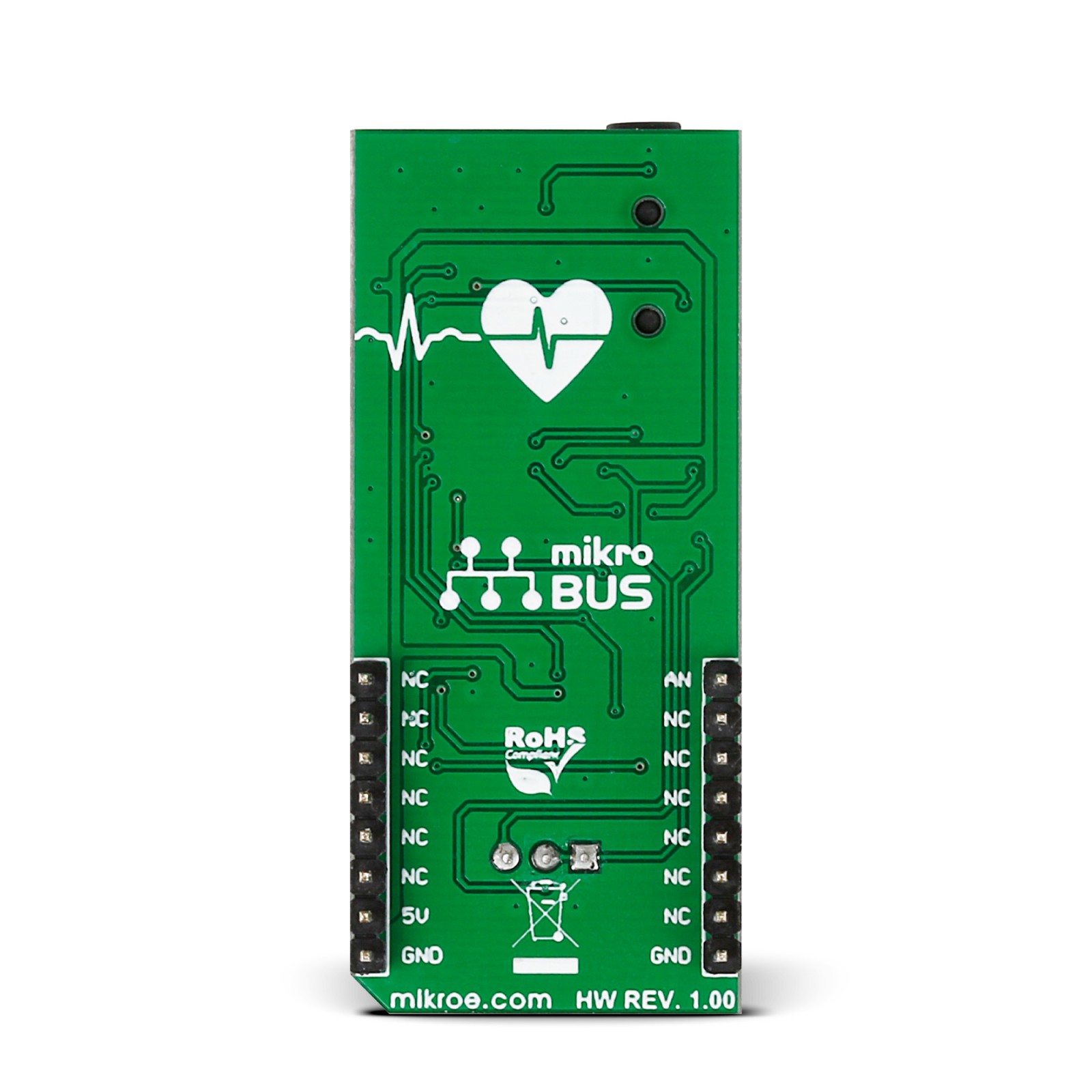
An onboard 3.5mm phone jack is used to connect cables/electrodes to the Click board™. The electrode collects voltage from the skin, after which the signal is amplified and filtered and then sent to the analog AN pin of the host MCU over the mikroBUS™ socket. The three electrodes should be placed on the left arm, right arm, and the left side of the abdomen (below the heart), on the left leg. ECG Click has one jumper and a trimmer potentiometer for setting the output voltage to match the input voltage level of the ADC which will be used (10-bit ADC – 12-bit recommended). As a reference, it uses the MAX6106, a low-cost, micropower, low-dropout, high-output-current voltage reference from Analog Devices. The SMD (0805) jumper determines its output voltage range. When connecting all three electrodes, the output should be a constant voltage (1.024V or 2.048V, depending on the jumper position).
The trimmer potentiometer is for adjusting the gain. So, if you set the jumper to the 2.048 position (zero is now 1.024V), the gain will be set so that the ECG waveform is in the range of 0-2.048V. If you set the jumper to the 4.096 position (zero is now 2.048V), the gain will be set so that the ECG waveform is in the range of 0-4.096V. The final measurement results can be displayed as an Electrocardiogram using a free app, the MikroPlot, a free data visualization tool (Windows). It’s a simple tool to help you visualize sensor data recorded over time, suitable for biosignals (ECG, EEG, EMG) and environmental data logging (temperature, humidity, and more). The app can receive data sets from a microcontroller through a USB UART connection. See the learn.mikroe.com article for more information.
This Click board™ can only be operated with a 5V logic voltage level. The board must perform appropriate logic voltage level conversion before using MCUs with different logic levels. However, the Click board™ comes equipped with a library containing functions and an example code that can be used, as a reference, for further development.
Specifications
Type
Biometrics,ECG
Applications
Can be used for the development of health-tracking and fitness devices, quantified-self wearables, portable battery-powered Holter, or you can just make an LED blink in sync with your heart
On-board modules
MCP609 – micropower CMOS operational amplifiers from Microchip
MAX6106 – micropower, low-dropout, high-output-current voltage reference from Analog Devices
Key Features
7-block design, selectable output voltage range, gain adjustment trimmer, 10-bit ADC, ready-to-use example and free software tool to generate ECG plot, DRL circuit, and more
Interface
Analog
Feature
No ClickID
Compatibility
mikroBUS™
Click board size
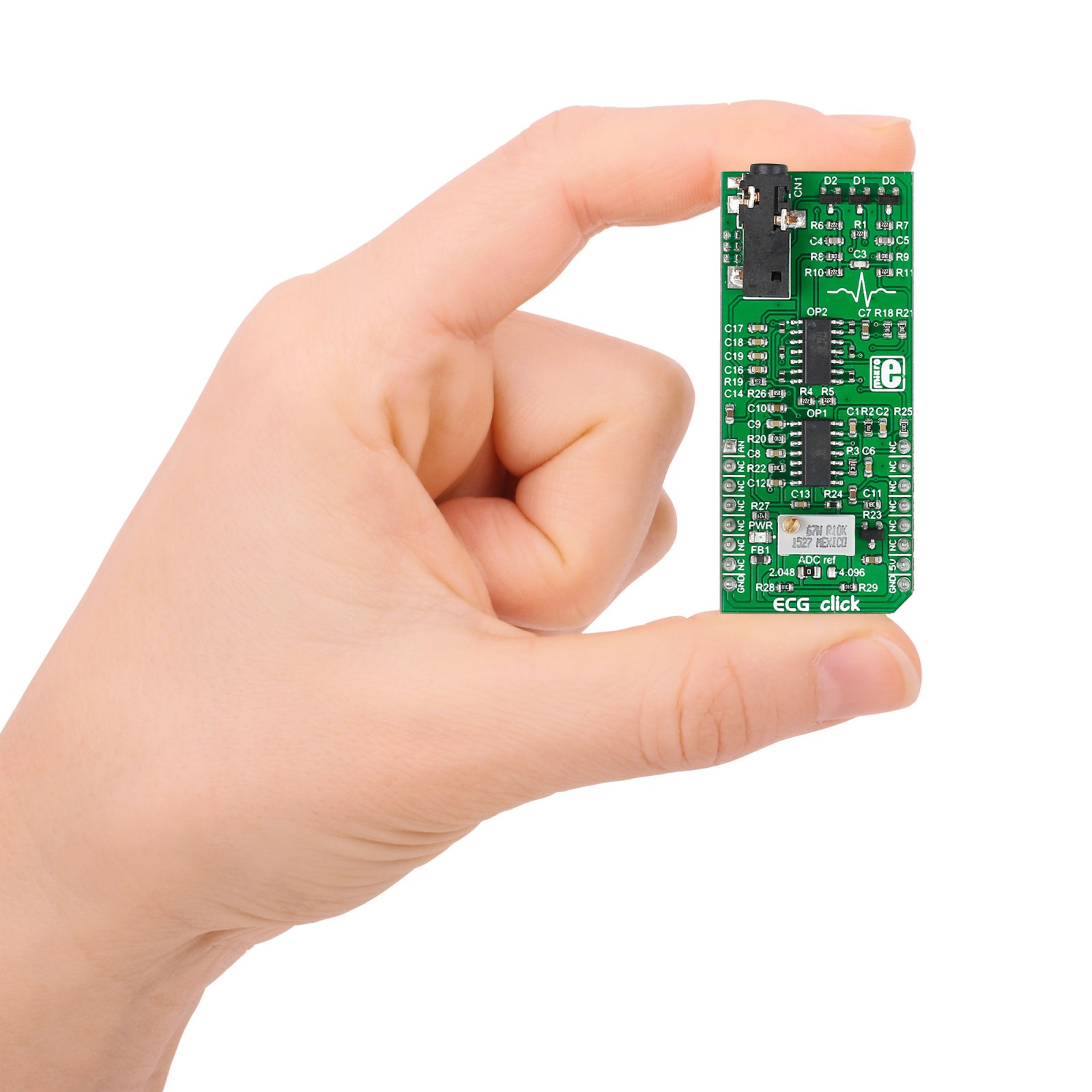
L (57.15 x 25.4 mm)
Input Voltage
5V
Pinout diagram
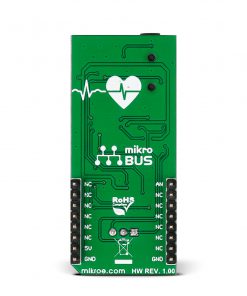
This table shows how the pinout on ECG Click corresponds to the pinout on the mikroBUS™ socket (the latter shown in the two middle columns).
Onboard settings and indicators
Label | Name | Default | Description |
---|---|---|---|
LD1 | PWR | – | Power LED Indicator |
JP1 | ADC ref | Left | Reference Voltage Selection 2.048/4.096: Left position 2.048, Right position 4.096 |
ECG Click electrical specifications
Description | Min | Typ | Max | Unit |
---|---|---|---|---|
Supply Voltage | – | 5 | – | V |
Software Support
We provide a library for the ECG Click as well as a demo application (example), developed using MIKROE compilers. The demo can run on all the main MIKROE development boards.
Package can be downloaded/installed directly from NECTO Studio Package Manager (recommended), downloaded from our LibStock™ or found on Mikroe github account.
Library Description
This library contains API for ECG Click driver.
Key functions
-
This function read ADC data.
-
This function executes default configuration for ECG click.
-
This function initializes all necessary pins and peripherals used for this click.
Example Description
This example demonstrates the use of ECG Click board.
void application_task ( void )
{
time_read++;
read_adc = ecg_generic_read( &ecg );
plot_res( read_adc , time_read);
Delay_ms(5);
}
The full application code, and ready to use projects can be installed directly from NECTO Studio Package Manager (recommended), downloaded from our LibStock™ or found on Mikroe github account.
Other Mikroe Libraries used in the example:
- MikroSDK.Board
- MikroSDK.Log
- Click.Ecg
Additional notes and informations
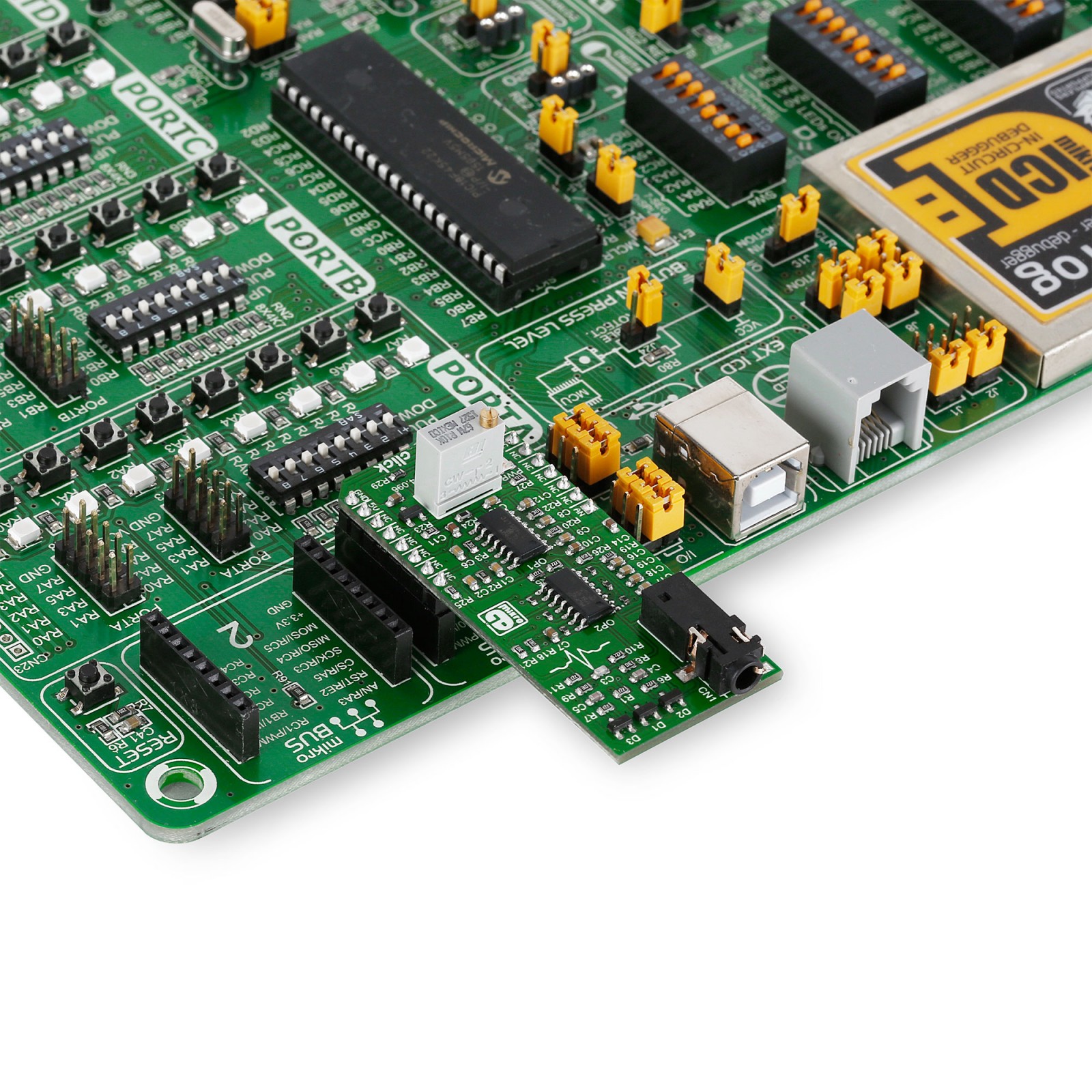
Depending on the development board you are using, you may need USB UART click, USB UART 2 Click or RS232 Click to connect to your PC, for development systems with no UART to USB interface available on the board. UART terminal is available in all MIKROE compilers.
mikroSDK
This Click board™ is supported with mikroSDK – MIKROE Software Development Kit. To ensure proper operation of mikroSDK compliant Click board™ demo applications, mikroSDK should be downloaded from the LibStock and installed for the compiler you are using.
For more information about mikroSDK, visit the official page.