DMX Click
R1,200.00 ex. VAT
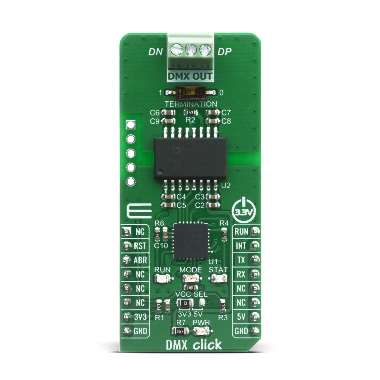
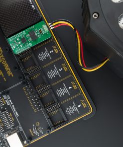
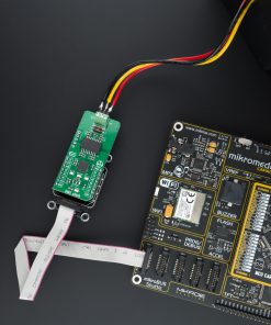
DMX Click is a device used to establish communication between the MCU and equipment that uses the DMX512-A communication protocol. Unlike many similar solutions on the market, this unique device allows using the common UART data format, which is converted to an appropriate DMX512 format by the powerful PIC18F26K42 MCU from Microchip. This MCU has an integrated DMX peripheral, making it a perfect solution for such application. To allow interfacing with the DMX bus, DMX Click uses the RS485 transceiver from Analog Devices. Besides providing single-ended to differential signal conversion, this IC also provides the complete galvanic isolation from the DMX bus, without using any additional isolation components.
DMX Click is supported by a mikroSDK compliant library, which includes functions that simplify software development. This Click board™ comes as a fully tested product, ready to be used on a system equipped with the mikroBUS™ socket.
Stock: Lead-time applicable.
| 5+ | R1,140.00 |
| 10+ | R1,080.00 |
| 15+ | R1,020.00 |
| 20+ | R981.60 |
How does it work?
Click board ™ can be used to create custom DMX512-A compatible equipment of any kind, allowing it to be easily operated from any device that can transmit UART data at any speed. It simplifies development, taking care of the low-level DMX512-A communication. DMX Click is especially suited for stage lighting applications, as it will never cause unintentional blackout if the input data stream becomes interrupted. It can be used for building and development of custom lighting applications for all kinds of stage lighting use cases.
DMX is an abbreviation for Digital Multiplex, and due to its robustness and immunity to EMI, this protocol is extensively used for controlling stage lighting equipment, including dimmers, spot-lights, fog machines, and similar equipment that is operated at low baud-rates, in a very noisy environment. The original DMX512 protocol was created in 1986. It was officially approved by the American National Standards Institute (ANSI) in 2004 and currently, the standard is known as “E1.11 – 2008, USITT DMX512-A”, or just “DMX512-A”. It is based on a fixed 250 kbps data rate transfer through the RS485 interface. The DMX512-A protocol allows a single MASTER device which sends data to multiple SLAVE devices, over 512 different channels.
DMX Click is equipped with two different ICs: the first one is the PIC18F26K42 from Microchip, which is, among other peripherals, equipped with a DMX512 (DMX) hardware module. This makes it a very robust alternative to many similar software-based solutions, which generate all the specific DMX timings by dynamically switching the UART baud rate, or by using some similar techniques. The second IC is the ADM2862E from Analog Devices, a very compact and robust RS485 transceiver, which provides up to 5kV of galvanic isolation between the bus and the controller side. The same IC was used in RS485 2 Click where you can find a brief explanation of its functionalities. More detailed information can be found in its official datasheet, in the links below.

The basic concept of DMX Click is to take plain UART data at any baud rate at its input and use it to fill in the channel data of any of the 512 available DMX slots, without worrying about timings, signal conversion, frame rates, etc. In other words, DMX Click supports controlling a single DMX Universe over the common UART interface found on almost every MCU, which opens up many design possibilities. It can be used to design an independent control desk (DMX MASTER), which doesn’t require a PC to be connected. It can also be used to design custom DMX SLAVE applications very easily.
The DMX protocol itself has some specifics, which need to be explained in order to better understand how the Click board™ works: the DMX data format is very similar to a common UART, except it is fixed to a data rate of 250kbps, one start bit, eight data bits, two stop bits and no parity. Data is sent in frames and each frame consists of:
- Break condition (BR)
- Mark-After-Break (MAB)
- Slot 0, containing the Start Code
- Up to 512 slots of channel data, each containing a single byte
Considering the fixed DMX baud rate, it takes approximately 23ms to send 513 bytes of data, along with BR and MAB signals, which translates to a maximum frame rate of 44 Hz. In other words, the channel data of a single slot can be updated 44 times per second. If higher frame rates are required (e.g. smoother movement, smoother light transition), the entire frame can be shortened. DMX512-A standard doesn’t require sending all 512 slots, which can save time between two frames.
DMX Click can be operated in both MASTER and SLAVE modes. It allows many of DMX parameters to be configured for each mode, by using simple UART commands interface. User can configure the frame length itself, gap length between two consecutive frames, number of channels within the frame, duration of the interrupt signal after each frame, and so on. The DMX Click Manual provides all the necessary information about the available parameters in both modes.
The firmware on the PIC26K42 MCU utilizes two memory buffers. Incoming data from the UART input is stored in the first buffer (A), while the second buffer (B) is transferred to the UART output. Data transfer is performed by using dedicated DMA channels. When the transfer is done and if the A buffer is full, the DMA transfer restarts, while the buffers are swapped. Now the buffer B is accepting data from the input, while the buffer A is transferred to the UART output. This is a typical double-buffering concept and it allows synchronization between two buffers working on different speeds.
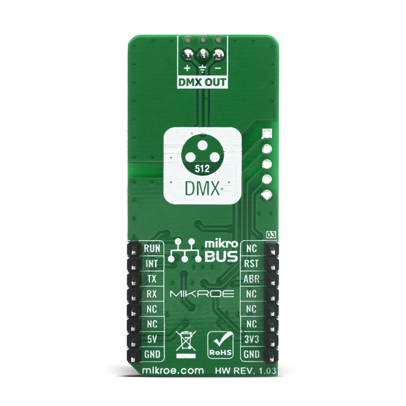
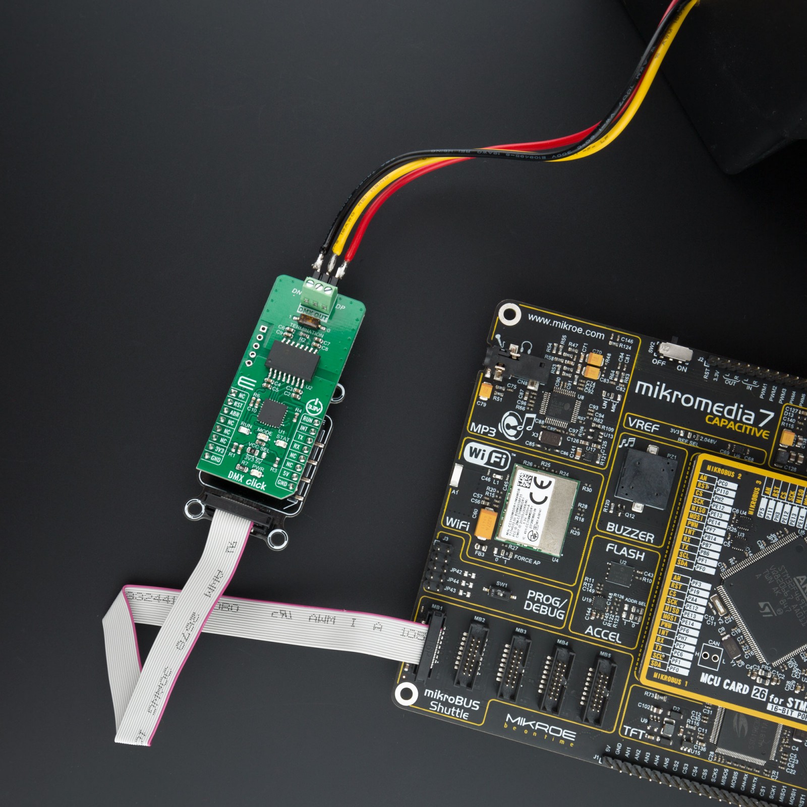
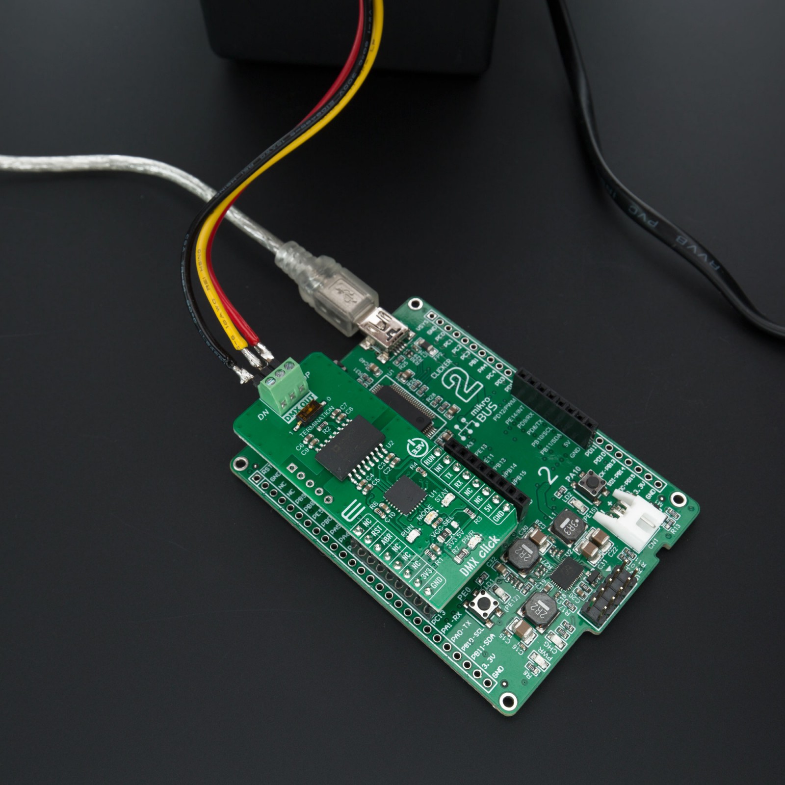
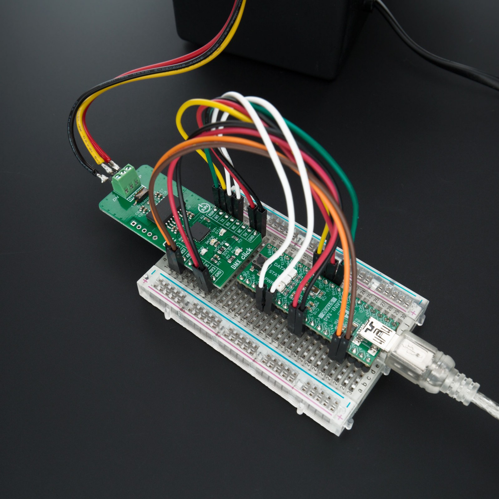
The input-side UART is configured to auto or fixed (115200) baud rate, while the output-side UART is set to a DMX mode and is routed to the RS485 transceiver. The 3-pole output terminal is used to connect the Click board™ to the DMX bus, with its connections clearly marked on the PCB (DN – Data Negative; DP – Data Positive; GND in the middle)
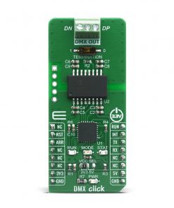
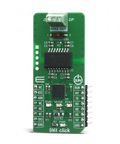
The interrupt pin (INT) is used to signalize different events to the host MCU, while the STAT LED is used as a visual indication (i.e. for config errors). The MODE LED indicates operating mode (SLAVE or MASTER), while the RUN LED indicates the running status of the Click board™. Please refer to the DMX Click Manual for a detailed explanation of DMX Click functions in each mode.
DMX Click offers a selection between 3.3V and 5V operation, with the onboard SMD jumper, labeled as PWR SEL. This allows both 3.3V and 5V MCUs to be interfaced with this Click board™.
Specifications
Type
DMX
Applications
Stage lighting applications, building and development of custom lighting applications for all kinds of stage lighting use cases.
On-board modules
ADM2862E – Power Isolated RS-485 Transceiver from Analog Devices
PIC18F26K42 – Low Power, High Performance MCU with XLP Technology, from Microchip
Key Features
Providing single-ended to differential signal conversion, galvanic isolation from the DMX bus, can be operated in both MASTER and SLAVE modes
Interface
GPIO,UART
Feature
No ClickID
Compatibility
mikroBUS™
Click board size
L (57.15 x 25.4 mm)
Input Voltage
3.3V,5V
Pinout diagram
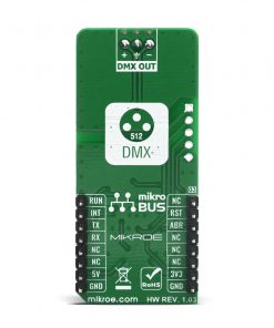
This table shows how the pinout on DMX Click corresponds to the pinout on the mikroBUS™ socket (the latter shown in the two middle columns).
Onboard settings and indicators
| Label | Name | Default | Description |
|---|---|---|---|
| LD1 | STAT | – | Status Indicator |
| LD2 | RUN | – | RUN Indicator |
| LD3 | MODE | – | MODE Indicator |
| LD4 | PWR | – | Power LED Indicator |
| JP1 | VCC SEL | Left | Power supply voltage selection: left position 3V3, right position 5V |
| SW1 | Termination | OFF | Termination resistor switch: left position 1, right position 0 |
Software Support
We provide a library for the DMX Click on our LibStock page, as well as a demo application (example), developed using MikroElektronika compilers. The demo can run on all the main MikroElektronika development boards.
Library Description
This library offers a choice to control stage lighting and effects. One master device can control one, two, or more slave devices. User can determine length of the DMX frame, speed of the DMX frame transfer, data length, start address, interrupt duration. Any DMX slave device (DMX Click board, RGB reflector) is determined by start address and data length. This data can consist of the, for example, color selection, light intensity, and many different effects. Master executes the DMX frame transfer, ‘0’ always be transfered first, and slave receives data from the sent frame starting from the determined start address, ‘0’ always be received first. This is a excellent solution to control stage lighting on the easy, simple and fast way. For more details check documentation.
Key functions:
void dmx_send_cmd( uint8_t *cmd, uint16_t cmd_len )– This function sends a command to the DMX device.void dmx_default_handler( void ( *handler )( uint8_t*, uint16_t*, uint8_t* ) )– This function sets handler on the function which should be performed, for example function for the results logging.void dmx_run( uint8_t run_mode )– This function allows user to put device in config or run mode.
Examples description
The application is composed of three sections :
- System Initialization – Initializes peripherals and pins.
- Application Initialization – Initializes UART serial interface and executes a device configuration and mode setting. In our example the device is configured as master and allows 5 data bytes transfer starting from the address 8. DMX frame length is 15, starting from 0, and range can be from 1 to 512. Start address can be from 1 to 512 also. @FTMR,nnn – determines the delay between two DMX frame, range is from 000 to 007 (from 20ms to 160ms). @ITMR,nnn – determines the duration of the interrupt signal, range is from 000 to 007 (from 0.1ms to 1.28ms).
- Application Task – (code snippet) – When device was configured as master, user can enter the desired 5 data bytes, that will be transfered to the slave every 140ms. When device was configured as slave, the device will receive 5 data bytes from the master, transfered from the address 8 to address 12, every 140ms (in this example). Note : RUN LED – DMX frame transfer indication STAT LED – interrupt indication MODE LED – indicates the device mode, when is set the device was configured as master, and when is reset the device was configured as slave.
void application_task( )
{
    if ( device_mode == DMX_SLAVE )
    {
        process( );
    }
    else if ( master_mode == DMX_MASTER_USER_CTRL )
    {
        uint8_t cmd_check;
        uint8_t tx_buff[ 6 ] = { 0 };

        mikrobus_logWrite( "> CH1 - light [0-255]: ", _LOG_TEXT );
        tx_buff[ 0 ] = enter_cmd( );

        mikrobus_logWrite( "> CH2 - red [0-255]: ", _LOG_TEXT );
        tx_buff[ 1 ] = enter_cmd( );

        mikrobus_logWrite( "> CH3 - green [0-255]: ", _LOG_TEXT );
        tx_buff[ 2 ] = enter_cmd( );

        mikrobus_logWrite( "> CH4 - blue [0-255]: ", _LOG_TEXT );
        tx_buff[ 3 ] = enter_cmd( );

        mikrobus_logWrite( "> CH5 - strobe [1-255]: ", _LOG_TEXT );
        tx_buff[ 4 ] = enter_cmd( );

        mikrobus_logWrite( "> CH6 - change colores [1-255]: ", _LOG_TEXT );
        tx_buff[ 5 ] = enter_cmd( );

        dmx_send_cmd( &tx_buff[ 0 ], 6 );
        cmd_check = dmx_check_int( );

        while ( cmd_check == DMX_INT_INACTIVE )
        {
            cmd_check = dmx_check_int( );
        }

        mikrobus_logWrite( "> command sent", _LOG_LINE );
        mikrobus_logWrite( "************************************", _LOG_LINE );
    }
    else
    {
        application_demo( );
    }
}
The full application code, and ready to use projects can be found on our LibStock page.
Other mikroE Libraries used in the example:
- Conversions
- C_String
- UART
Additional notes and informations
Depending on the development board you are using, you may need USB UART click, USB UART 2 click or RS232 click to connect to your PC, for development systems with no UART to USB interface available on the board. The terminal available in all MikroElektronika compilers, or any other terminal application of your choice, can be used to read the message.
mikroSDK
This Click board™ is supported with mikroSDK – MikroElektronika Software Development Kit. To ensure proper operation of mikroSDK compliant Click board™ demo applications, mikroSDK should be downloaded from the LibStock and installed for the compiler you are using.
For more information about mikroSDK, visit the official page.
Resources
Downloads
| Weight | 18 g |
|---|---|
| Brand | MikroElektronika |

