How does it work?
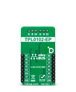
DIGI POT 14 Click is based on the TPL0102, a dual-channel digital potentiometer with non-volatile memory from Texas Instruments. It is a two-channel linear-taper digital potentiometer. Each potentiometer can be used as a three-terminal potentiometer or a two-terminal rheostat. When the TPL0102 is powered down, it saves the last values of wipers in EEPROM, and when the power is restored, the positions of wipers are loaded to their initial position. The TPL0102 features a fast power-up response time to wiper settings under 100μs, single-supply, and dual-supply operation ranges.
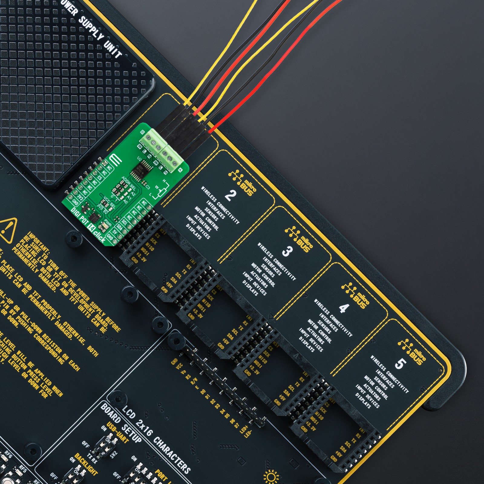
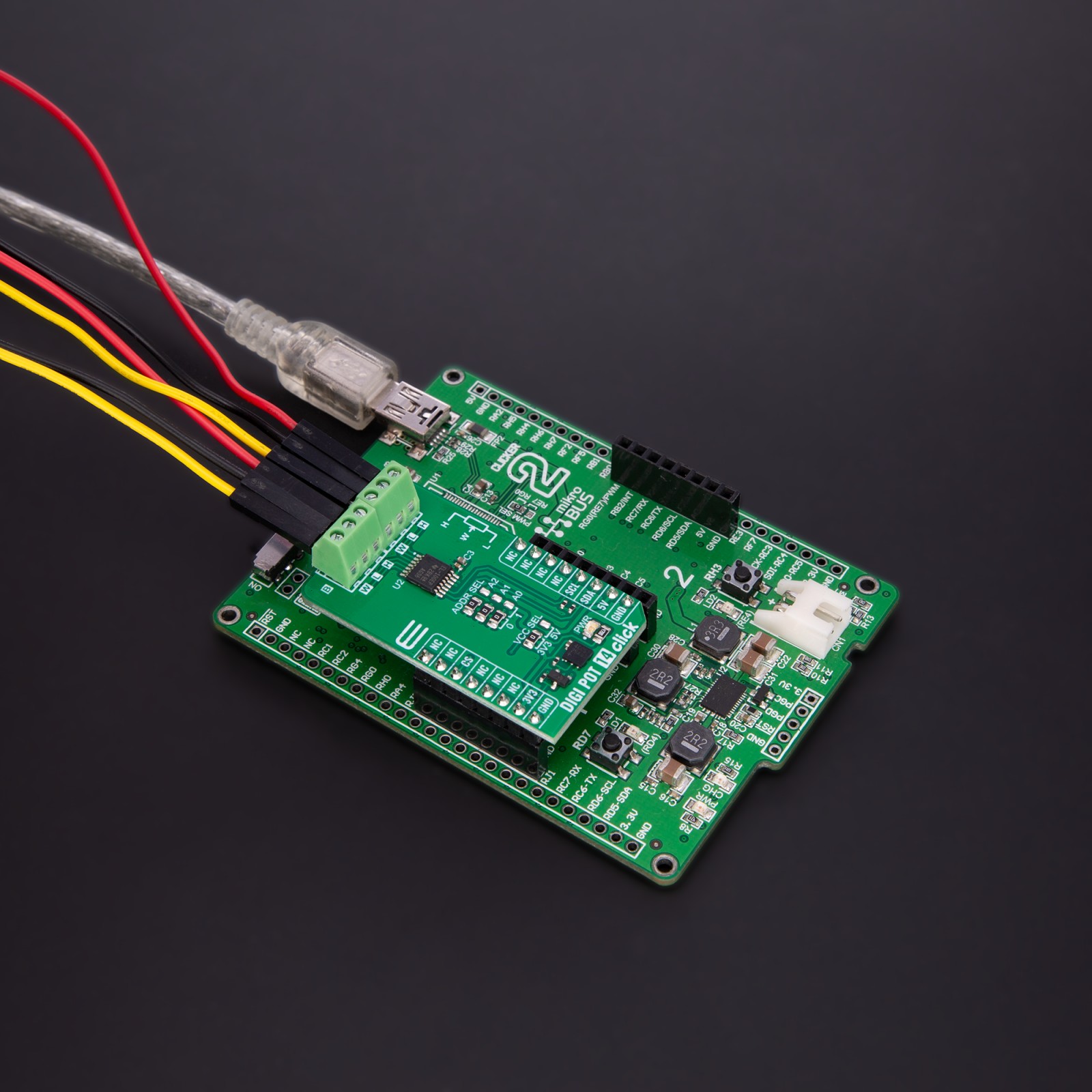
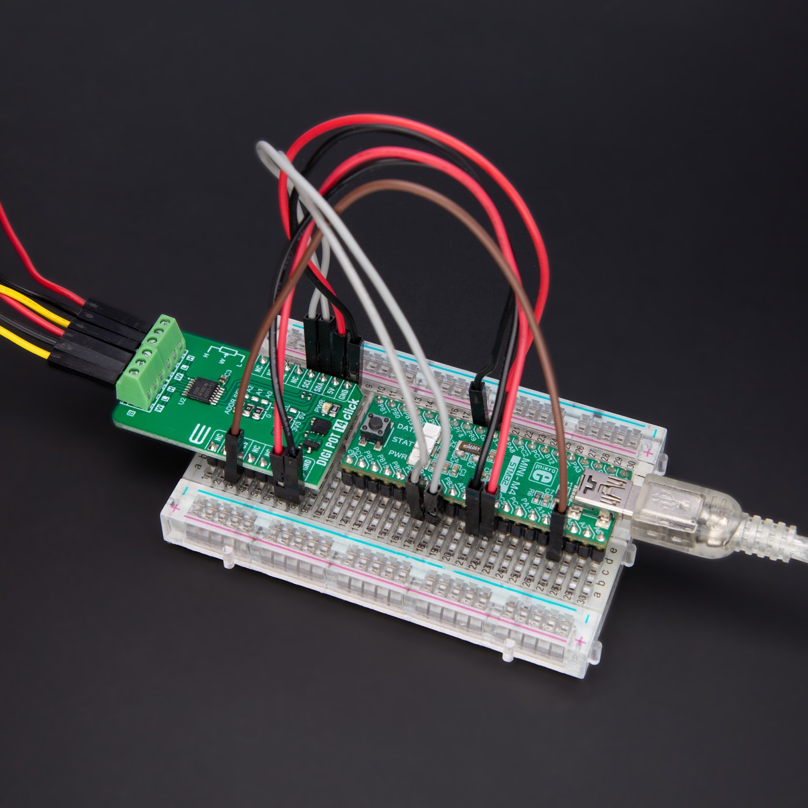
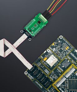
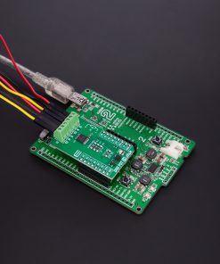
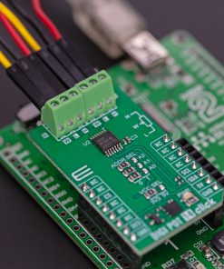
DIGI POT 14 Click uses a standard 2-Wire I2C interface to communicate with the host MCU and supports Standard and Fast mode with up to 400kHz of clock frequency. The I2C address can be set over the ADDR SEL jumpers, where 0 is set by default. Both potentiometers’ high, low, and wiper pins are tied to screw terminals, properly labeled as A and B sides.
This Click board™ can operate with either 3.3V or 5V logic voltage levels selected via the VCC SEL jumper. This way, both 3.3V and 5V capable MCUs can use the communication lines properly. Also, this Click board™ comes equipped with a library containing easy-to-use functions and an example code that can be used as a reference for further development.
Specifications
Type
Digital potentiometer
Applications
Can be used for developing adjustable gain amplifiers and offset timing, adjustable power supplies, precision calibration of set point thresholds, sensor timing and calibration, and more
On-board modules
TPL0102 – dual-channel digital potentiometer with non-volatile memory from Texas Instruments
Key Features
Dual-channel, linear-taper digital potentiometer, can be used as a three-terminal potentiometer, or a two-terminal rheostat, non-volatile memory for storing wiper position, 256-position resolution, single-supply, fast power-up response time to wiper settings, 100K end-to-end resistance, and more
Interface
I2C
Feature
ClickID
Compatibility
mikroBUS™
Click board size
M (42.9 x 25.4 mm)
Input Voltage
3.3V or 5V
Pinout diagram
This table shows how the pinout on DIGI POT 14 Click corresponds to the pinout on the mikroBUS™ socket (the latter shown in the two middle columns).
Onboard settings and indicators
Label | Name | Default | Description |
---|---|---|---|
LD1 | PWR | – | Power LED Indicator |
JP1 | VCC SEL | Left | Power/Logic Voltage Level Selection 3V3/5V: Left position 3V3, Right position 5V |
JP2-JP4 | ADDR SEL | Left | I2C Address Selection 0/1: Left position 0, Right position 1 |
Software Support
We provide a library for the DIGI POT 14 Click as well as a demo application (example), developed using MIKROE compilers. The demo can run on all the main MIKROE development boards.
Package can be downloaded/installed directly from NECTO Studio Package Manager (recommended), downloaded from our LibStock™ or found on Mikroe github account.
Library Description
This library contains API for DIGI POT 14 Click driver.
Key functions
-
digipot14_reg_write
DIGI POT 14 register write function. -
digipot14_set_pot_a_wiper
DIGI POT 14 set the wiper position of potentiometer A function. -
digipot14_set_pot_b_wiper
DIGI POT 14 set the wiper position of potentiometer B function.
Example Description
This library contains API for DIGI POT 14 Click driver. The demo application uses a digital potentiometer to change the resistance values.
void application_task ( void )
{
for ( uint8_t wiper_val = DIGIPOT14_MIN_POSITION; wiper_val <= DIGIPOT14_MAX_POSITION; wiper_val++ )
{
digipot14_set_pot_a_wiper( &digipot14, wiper_val );
digipot14_set_pot_b_wiper( &digipot14, wiper_val );
log_printf( &logger, " Resistance = %.3f KOhm rn",
( DIGIPOT14_MAX_RESISTANCE_KOHM * ( wiper_val / DIGIPOT14_MAX_POSITION_NUM ) ) );
Delay_ms( 1000 );
}
}
The full application code, and ready to use projects can be installed directly from NECTO Studio Package Manager (recommended), downloaded from our LibStock™ or found on Mikroe github account.
Other Mikroe Libraries used in the example:
- MikroSDK.Board
- MikroSDK.Log
- Click.DIGIPOT14
Additional notes and informations
Depending on the development board you are using, you may need USB UART click, USB UART 2 Click or RS232 Click to connect to your PC, for development systems with no UART to USB interface available on the board. UART terminal is available in all MIKROE compilers.
mikroSDK
This Click board™ is supported with mikroSDK – MIKROE Software Development Kit. To ensure proper operation of mikroSDK compliant Click board™ demo applications, mikroSDK should be downloaded from the LibStock and installed for the compiler you are using.
For more information about mikroSDK, visit the official page.