How does it work?
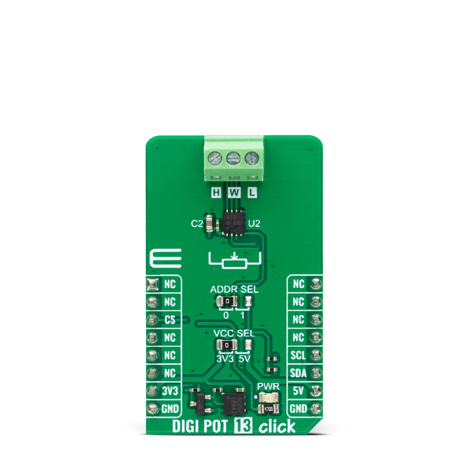
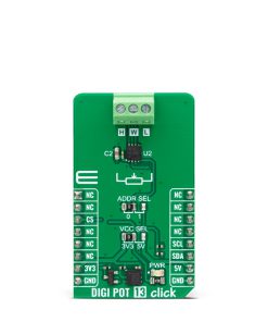
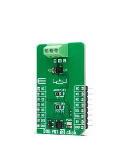
DIGI POT 13 Click is based on the MAX5419, a 256-tap non-volatile digital potentiometer from Analog Devices. It can perform as a discrete potentiometer or variable resistor. The potentiometers consist of a resistor array with 255 fixed resistor elements in series between appropriate H and L terminals. The potentiometer wiper (W) terminal is programmable to access any one of the 256 tap points on the resistor string, with typically 325 ohms of wiper resistance and 150-250kΩ of end-to-end resistance (200kΩ typical). It also features a power-on reset circuitry that loads the wiper position from non-volatile memory at power up. The memory is guaranteed for 50 years for wiper data retention and up to 200.000 wiper store cycles.
DIGI POT 13 Click communicates with the host MCU using the standard I2C 2-Wire interface, with a maximum clock frequency in Fast data transfer of up to 400KHz (400kbps). The I2C address can be selected via the ADDR SEL jumper with 0 selected by default. Over the I2C interface, all data can be stored in an internal 8-bit EEPROM.
This Click board™ can operate with either 3.3V or 5V logic voltage levels selected via the VCC SEL jumper. This way, both 3.3V and 5V capable MCUs can use the communication lines properly. However, the Click board™ comes equipped with a library containing easy-to-use functions and an example code that can be used, as a reference, for further development.
Specifications
Type
Digital potentiometer
Applications
Can be used for the development of mechanical potentiometer replacements for the portable consumer market, volume control, LCD contrast control, and battery-backup industrial applications
On-board modules
MAX5419 – digital potentiometer from Analog Devices
Key Features
Single channel, single supply operation, 256-position resolution, 200kΩ nominal resistance, I2C-compatible interface, nonvolatile memory stores wiper settings, 50 years of typical data retention, and more
Interface
I2C
Feature
No ClickID
Compatibility
mikroBUS™
Click board size
M (42.9 x 25.4 mm)
Input Voltage
3.3V or 5V
Pinout diagram
This table shows how the pinout on DIGI POT 13 Click corresponds to the pinout on the mikroBUS™ socket (the latter shown in the two middle columns).
Onboard settings and indicators
Label | Name | Default | Description |
---|---|---|---|
LD1 | PWR | – | Power LED Indicator |
JP1 | VCC SEL | Left | Logic Level Voltage Selection 3V3/5V: Left position 3V3, Right position 5V |
JP2 | ADDR SEL | Left | I2C Address Selection 0/1: Left position 0, Right position 1 |
DIGI POT 13 Click electrical specifications
Description | Min | Typ | Max | Unit |
---|---|---|---|---|
Supply Voltage | 3.3 | – | 5 | V |
Nominal Resistance | – | 200 | – | kΩ |
Resolution | – | 256 | – | taps |
Wiper Resistance | – | 325 | – | Ω |
Software Support
We provide a library for the DIGI POT 13 Click as well as a demo application (example), developed using MIKROE compilers. The demo can run on all the main MIKROE development boards.
Package can be downloaded/installed directly from NECTO Studio Package Manager (recommended), downloaded from our LibStock™ or found on Mikroe github account.
Library Description
This library contains API for DIGI POT 13 Click driver.
Key functions
-
digipot13_set_resistance
DIGI POT 13 set the resistance function. -
digipot13_set_wiper_pos
DIGI POT 13 set the wiper position function. -
digipot13_write_data
DIGI POT 13 write data function.
Example Description
This library contains API for DIGI POT 13 Click driver. The demo application uses a digital potentiometer to change the resistance values.
void application_task ( void )
{
for ( uint8_t res_kohm = DIGIPOT13_RES_0_KOHM; res_kohm <= DIGIPOT13_RES_200_KOHM; res_kohm += DIGIPOT13_RES_50_KOHM )
{
if ( DIGIPOT13_OK == digipot13_set_resistance( &digipot13, DIGIPOT13_CFG_RES_WH, ( float ) res_kohm ) )
{
log_printf( &logger, " Resistance: %.1f kOhmrn", ( float ) res_kohm );
log_printf( &logger, " ----------------------------rn" );
Delay_ms( 5000 );
}
}
}
The full application code, and ready to use projects can be installed directly from NECTO Studio Package Manager (recommended), downloaded from our LibStock™ or found on Mikroe github account.
Other Mikroe Libraries used in the example:
- MikroSDK.Board
- MikroSDK.Log
- Click.DIGIPOT13
Additional notes and informations
This Click board™ is supported with mikroSDK – MIKROE Software Development Kit, that needs to be downloaded from the LibStock and installed for the compiler you are using to ensure proper operation of mikroSDK compliant Click board™ demo applications.
mikroSDK
This Click board™ is supported with mikroSDK – MIKROE Software Development Kit, that needs to be downloaded from the LibStock and installed for the compiler you are using to ensure proper operation of mikroSDK compliant Click board™ demo applications.
For more information about mikroSDK, visit the official page.