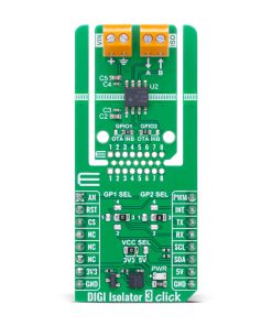
DIGI Isolator 3 Click
R255.00 ex. VAT
DIGI Isolator 3 Click is a compact add-on board used for isolating digital signals between two circuit sections, ensuring protection and signal integrity. This board features the ISO6521, a dual-channel digital isolator from Texas Instruments, designed for general-purpose signal isolation in non-safety applications. The board features two unidirectional isolation channels, supports data rates up to 50Mbps, and operates with independent power supplies ranging from 1.71V to 5.5V. It offers strong immunity to electromagnetic interference, a default HIGH fail-safe output, and flexible signal selection via jumpers. DIGI Isolator 3 Click is ideal for applications such as power supplies, electricity meters, motor drivers, factory and building automation, lighting systems, and smart appliances.
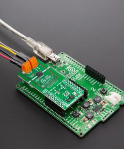
DIGI Isolator 3 Click is fully compatible with the mikroBUS™ socket and can be used on any host system supporting the mikroBUS™ standard. It comes with the mikroSDK open-source libraries, offering unparalleled flexibility for evaluation and customization. What sets this Click board™ apart is the groundbreaking ClickID feature, enabling your host system to seamlessly and automatically detect and identify this add-on board.
Stock: Lead-time applicable.
| 5+ | R242.25 |
| 10+ | R229.50 |
| 15+ | R216.75 |
| 20+ | R208.59 |
How does it work?
DIGI Isolator 3 Click is based on the ISO6521, a dual-channel digital isolator from Texas Instruments designed for general-purpose signal isolation in non-safety applications. This high-performance component ensures reliable operation across a wide range of industrial and embedded systems by providing electrical isolation between two sides of a circuit, breaking ground loops and protecting sensitive components from noise and transient voltages. Engineered to deliver strong immunity against electromagnetic interference while keeping emissions at a minimum, the ISO6521 ensures dependable operation in noisy environments. This makes DIGI Isolator 3 Click ideal for use in a variety of applications including power supplies, electricity metering systems, motor control units, industrial and building automation, lighting systems, smart appliances, and any application where protection and signal integrity are essential.

At its core, the ISO6521 integrates two unidirectional isolation channels, with one channel dedicated to each direction, allowing bidirectional communication while maintaining isolation. Each channel features a logic input and output buffer that are galvanically separated by TI’s advanced silicon dioxide (SiO2) double capacitive isolation technology. This structure enables the ISO6521 to support a working voltage of up to 200VRMS or 280VDC, and withstand transient overvoltages up to 570VRMS or 800VDC for up to 60 seconds. The device operates at data rates of up to 50Mbps, making it suitable for high-speed communication between system blocks.
One of the key advantages of DIGI Isolator 3 Click lies in its flexible power supply configuration. Thanks to the isolated design, both sides of the ISO6521 can be powered independently within a wide supply voltage range of 1.71V to 5.5V, making it highly adaptable for use as both a logic level translator and an isolator. Furthermore, the isolator ensures a default HIGH output in the event of input power or signal loss, adding an extra layer of stability and fault tolerance to critical communication lines.
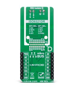
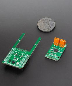
This Click board™ is designed in a unique format supporting the newly introduced MIKROE feature called “Click Snap.” Unlike the standardized version of Click boards, this feature allows the main IC area to become movable by breaking the PCB, opening up many new possibilities for implementation. Thanks to the Snap feature, the ISO6521 can operate autonomously by accessing its signals directly on the pins marked 1-8. Additionally, the Snap part includes a specified and fixed screw hole position, enabling users to secure the Snap board in their desired location.
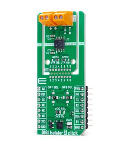
Signal selection for isolation on the DIGI Isolator 3 Click is configured using two 4-position jumpers labeled GP1 SEL and GP2 SEL. These jumpers allow the user to choose which signals from the mikroBUS™ socket will be routed to the input/output channels of the isolator. The GP1 SEL jumper offers a selection among the RST, SCL, RX, and PWM signals, corresponding to positions 1 through 4 respectively, while the GP2 SEL jumper provides the same selection method for the AN, SDA, TX, and INT signals. Once the desired signals are selected using the GPx SEL jumpers, the final configuration step is done through the GPIO1 and GPIO2 jumpers located in the Snap section of the board. These jumpers determine which of the previously selected signals will actually be isolated and routed through the A/B I/O channels of the ISO6521 isolator.
This Click board™ can operate with either 3.3V or 5V logic voltage levels selected via the VCC SEL jumper. This way, both 3.3V and 5V capable MCUs can use the communication lines properly. Also, this Click board™ comes equipped with a library containing easy-to-use functions and an example code that can be used as a reference for further development.
Specifications
Type
Isolators,Port expander
Applications
Ideal for applications such as power supplies, electricity meters, motor drivers, factory and building automation, lighting systems, and smart appliances
On-board modules
ISO6521 – dual-channel digital isolator from Texas Instruments
Key Features
Dual-channel digital isolator, general-purpose signal isolation, up to 50Mbps data rate, high EMI immunity, low emissions, default HIGH output on fault, Click Snap detachable section with standalone operation, and more
Interface
Analog,GPIO,I2C,PWM,UART
Feature
Click Snap,ClickID
Compatibility
mikroBUS™
Click board size
L (57.15 x 25.4 mm)
Input Voltage
3.3V or 5V,External
Pinout diagram
This table shows how the pinout on DIGI Isolator 3 Click corresponds to the pinout on the mikroBUS™ socket (the latter shown in the two middle columns).
| Notes | Pin | Pin | Notes | ||||
|---|---|---|---|---|---|---|---|
| Analog Output | AN | 1 | AN | PWM | 16 | PWM | PWM Signal |
| Reset | RST | 2 | RST | INT | 15 | INT | Interrupt |
| ID COMM | CS | 3 | CS | RX | 14 | TX | UART TX |
| NC | 4 | SCK | TX | 13 | RX | UART RX | |
| NC | 5 | MISO | SCL | 12 | SCL | I2C Clock | |
| NC | 6 | MOSI | SDA | 11 | SDA | I2C Data | |
| Power Supply | 3.3V | 7 | 3.3V | 5V | 10 | 5V | Power Supply |
| Ground | GND | 8 | GND | GND | 9 | GND | Ground |
Onboard settings and indicators
| Label | Name | Default | Description |
|---|---|---|---|
| LD1 | PWR | – | Power LED Indicator |
| JP1 | VCC SEL | Left | Power Voltage Level Selection 3V3/5V: Left position 3V3, Right position 5V |
|
JP2 |
GP1 SEL | Right | mikroBUS Signal Selection RST/SCL/RX/PWM: Left position RST, Lower position SCL, Right position RX, Upper position PWM |
|
JP4 |
GP2 SEL | Right | mikroBUS Signal Selection AN/SDA/TX/INT: Left position AN, Lower position SDA, Right position TX, Upper position INT |
|
JP3 |
GPIO1 | Right | Isolated I/O Channel Selection OTA/INB: Left position OTA, Right position INB |
|
JP5 |
GPIO2 | Left | Isolated I/O Channel Selection OTA/INB: Left position OTA, Right position INB |
DIGI Isolator 3 Click electrical specifications
| Description | Min | Typ | Max | Unit |
|---|---|---|---|---|
| Supply Voltage | 3.3 | – | 5 | V |
| External Power Supply | 1.71 | – | 5.5 | V |
| Data Rate | – | – | 50 | Mbps |
Software Support
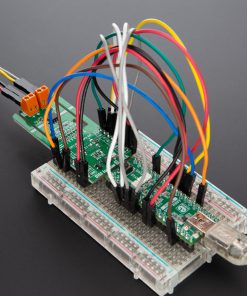
DIGI Isolator 3 Click demo application is developed using the NECTO Studio, ensuring compatibility with mikroSDK‘s open-source libraries and tools. Designed for plug-and-play implementation and testing, the demo is fully compatible with all development, starter, and mikromedia boards featuring a mikroBUS™ socket.
Example Description
This example demonstrates the use of an DIGI Isolator 3 Click board by showing the communication between the two Click board configured as a receiver and transmitter.
Key Functions
digiisolator3_cfg_setupThis function initializes Click configuration structure to initial values.digiisolator3_initThis function initializes all necessary pins and peripherals used for this Click board.digiisolator3_generic_writeThis function writes a desired number of data bytes by using UART serial interface.digiisolator3_generic_readThis function reads a desired number of data bytes by using UART serial interface.
Application Init
Initializes the driver and logger and displays the selected application mode.
Application Task
Depending on the selected mode, it reads all the received data or sends the desired message every 2 seconds.
Application Output
This Click board can be interfaced and monitored in two ways:
- Application Output – Use the “Application Output” window in Debug mode for real-time data monitoring. Set it up properly by following this tutorial.
- UART Terminal – Monitor data via the UART Terminal using a USB to UART converter. For detailed instructions, check out this tutorial.
Additional Notes and Information
The complete application code and a ready-to-use project are available through the NECTO Studio Package Manager for direct installation in the NECTO Studio. The application code can also be found on the MIKROE GitHub account.
Resources
Downloads
| Weight | 20 g |
|---|---|
| Brand | MikroElektronika |