How does it work?
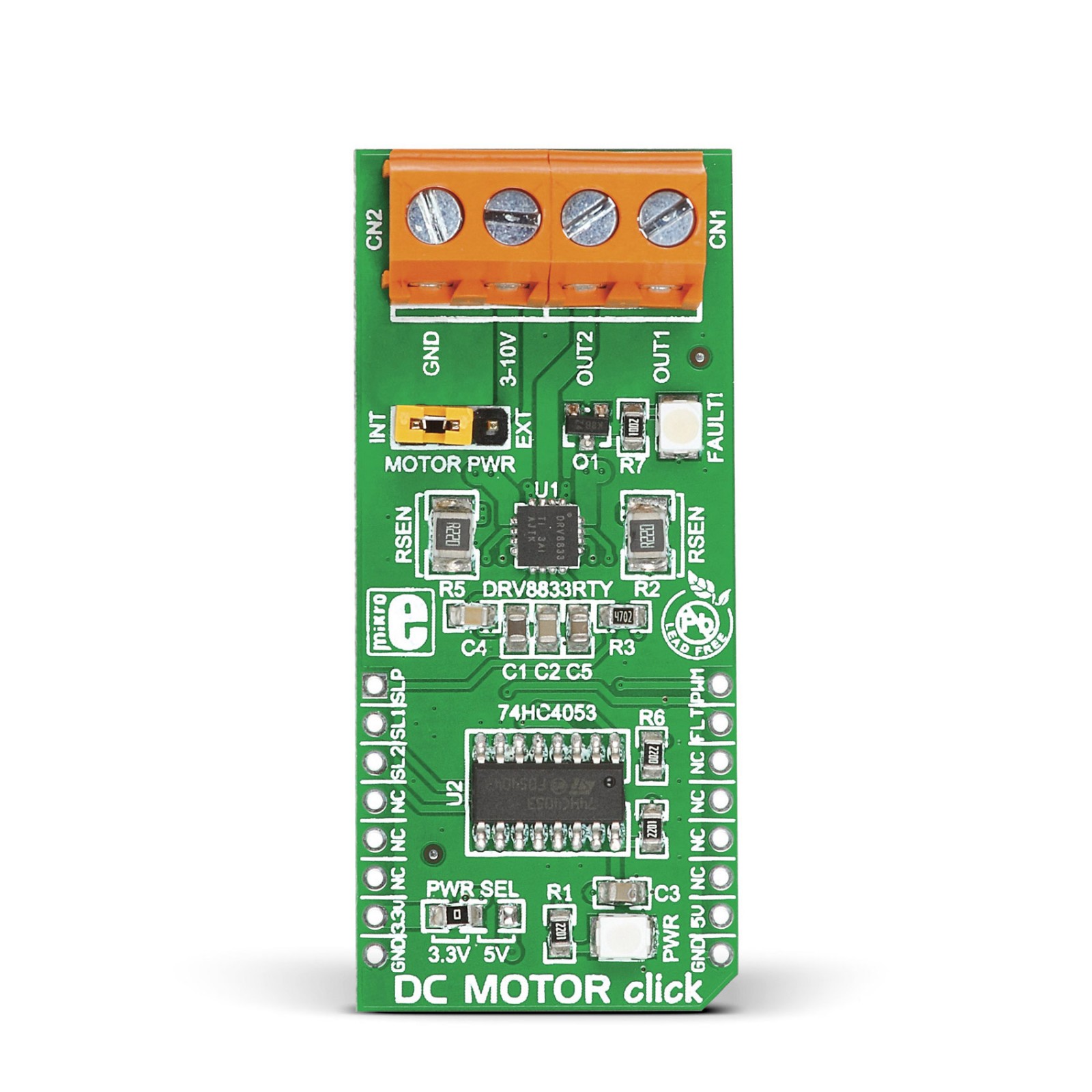
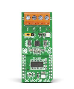
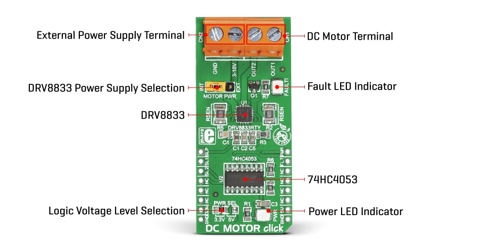
DC Motor Click is based on the DRV8833, an H-bridge motor driver with current-control PWM circuitry from Texas Instruments. The DRV8833 has two integrated H-bridges connected in parallel for double the current of a single H-bridge rated for an operating voltage range from 3V to 10V. The output driver block of the DRV8833 consists of N-channel power MOSFETs configured as an H-bridge to drive the motor windings, where each H-bridge includes circuitry to regulate or limit the winding current. Thanks to the current sense resistors R2 and R5 of 220mΩ, the driving current is limited to a value of 0.9A.
In addition, the 74HC4053 is also incorporated into the design to run the motor with only one PWM line from the mikroBUS™ socket. Thanks to this multiplexer, in combination with the selection pins SL1 and SL2, routed to the RST and CS pins of the mikroBUS™ socket, control of the DRV8833 driver as well as management of its operating modes (Coast/Fast Decay, Reverse, Forward, Brake/Slow Decay) is enabled. This mux can also be used for PWM control of the motor speed.
The DRV8833 also has a complete set of diagnostic and protection capabilities that support robust and reliable operation, like over-current protection, short circuit protection, undervoltage lockout, and overtemperature. In any case, the user can also visually detect them, in addition to the FLT pin, through the red LED marked with FAULT. It is also possible to set the driver in low power Sleep mode via the SLP pin routed to the AN pin of the mikroBUS™ socket. In this state, the H-bridges are disabled, the gate drive charge pump is stopped, all internal logic is reset, and all internal clocks are stopped.
This Click board™ can operate with both 3.3V and 5V logic voltage levels selected via the PWR SEL jumper. It allows both 3.3V and 5V capable MCUs to use the communication lines properly. Additionally, there is a possibility for the DRV8833 power supply selection via jumper labeled as MOTOR PWR to supply the DRV8833 from an external power supply terminal from 3V to 10V or from mikroBUS™ power rails. However, the Click board™ comes equipped with a library containing easy-to-use functions and an example code that can be used, as a reference, for further development.
Specifications
Type
Brushed
Applications
Can be used for driving DC brushed motors for toys, printers, and other mechatronic applications
On-board modules
DRV8833 – H-bridge motor driver with current-control PWM circuitry from Texas Instruments
Key Features
Low power consumption, driver for one DC motor, PWM and GPIO based control over motor velocity and direction, full protection and diagnostics, and more
Interface
GPIO,PWM
Feature
No ClickID
Compatibility
mikroBUS™
Click board size
L (57.15 x 25.4 mm)
Input Voltage
3.3V or 5V
Pinout diagram
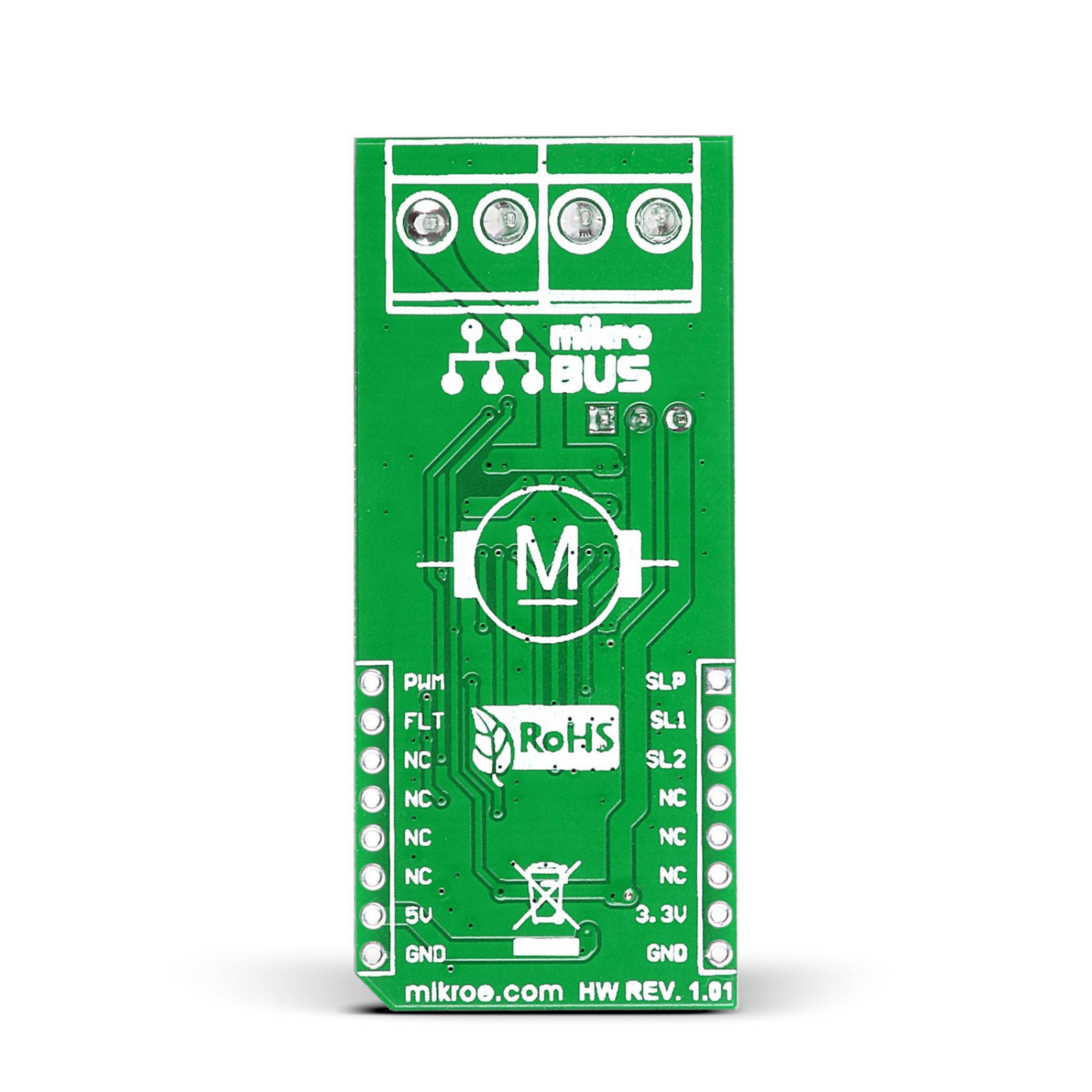
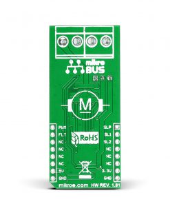
This table shows how the pinout on DC MOTOR Click corresponds to the pinout on the mikroBUS™ socket (the latter shown in the two middle columns).
Onboard settings and indicators
Label | Name | Default | Description |
---|---|---|---|
LD1 | PWR | – | Power LED Indicator |
LD2 | FAULT | – | Fault LED Indicator |
JP1 | PWR SEL | Left | Logic Level Voltage Selection 3V3/5V: Left position 3V3, Right position 5V |
JP2 | MOTOR PWR | Right | DRV8833 Power Supply Selection INT/EXT: Left position INT, Right position EXT |
DC MOTOR Click electrical specifications
Description | Min | Typ | Max | Unit |
---|---|---|---|---|
Supply Voltage | 3.3 | – | 5 | V |
External Supply Voltage Range | 3 | – | 10 | V |
Maximum Output Current | – | – | 3 | A |
Software Support
We provide a library for the DC MOTOR Click as well as a demo application (example), developed using MikroElektronika compilers. The demo can run on all the main MikroElektronika development boards.
Package can be downloaded/installed directly from NECTO Studio Package Manager(recommended way), downloaded from our LibStock™ or found on Mikroe github account.
Library Description
This library contains API for DC MOTOR Click driver.
Key functions
-
Start PWM module.
-
Enable the motor function.
-
Set sleep mode function.
Example Description
This application change the speed and direction of DC Motor.
void application_task ( void )
{
// Task implementation.
if ( duty_cycle > dcmotor.pwm_period )
{
duty_cycle = 100;
}
dcmotor_set_duty_cycle ( &dcmotor, duty_cycle );
duty_cycle += 50;
Delay_100ms();
log_printf( &logger, " Left Direction rn" );
dcmotor_left_direction_slow( &dcmotor );
dcmotor_enable( &dcmotor );
Delay_ms( 1000 );
for ( duty_cycle = 500; duty_cycle < 3000; duty_cycle += 250 )
{
dcmotor_set_duty_cycle( &dcmotor, duty_cycle );
log_printf( &logger, " <rn" );
Delay_ms( 1000 );
}
dcmotor_sleep_mode( &dcmotor );
Delay_ms( 1000 );
log_printf( &logger, "---------------------rn" );
log_printf( &logger, " Right Direction rn" );
dcmotor_right_direction_fast( &dcmotor );
dcmotor_enable( &dcmotor );
Delay_ms( 1000 );
for ( duty_cycle = 500; duty_cycle < 3000; duty_cycle += 250 )
{
dcmotor_set_duty_cycle( &dcmotor, duty_cycle );
log_printf( &logger, " >rn" );
Delay_ms( 1000 );
}
log_printf( &logger, "---------------------rn" );
dcmotor_sleep_mode( &dcmotor );
Delay_ms( 1000 );
}
The full application code, and ready to use projects can be installed directly from NECTO Studio Package Manager(recommended way), downloaded from our LibStock™ or found on Mikroe github account.
Other Mikroe Libraries used in the example:
- MikroSDK.Board
- MikroSDK.Log
- Click.DcMotor
Additional notes and informations
Depending on the development board you are using, you may need USB UART click, USB UART 2 Click or RS232 Click to connect to your PC, for development systems with no UART to USB interface available on the board. UART terminal is available in all MikroElektronika compilers.
mikroSDK
This Click board™ is supported with mikroSDK – MikroElektronika Software Development Kit. To ensure proper operation of mikroSDK compliant Click board™ demo applications, mikroSDK should be downloaded from the LibStock and installed for the compiler you are using.
For more information about mikroSDK, visit the official page.