How does it work?
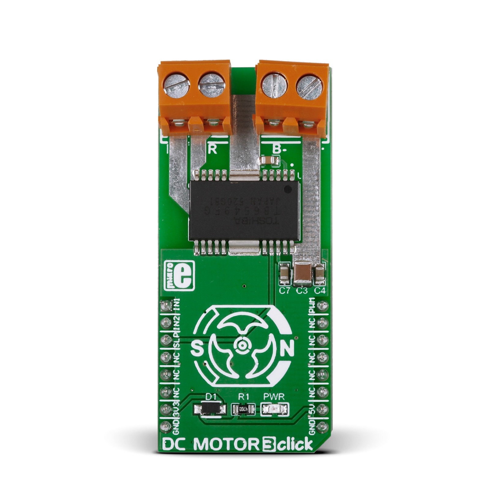
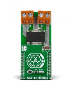
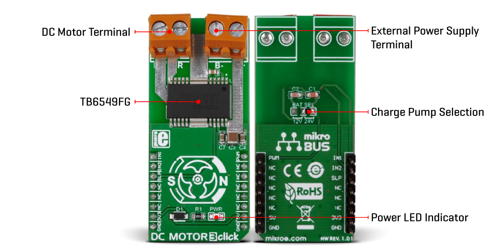
DC MOTOR 3 Click is based on the TB6549FG, a full-bridge driver for direct current motors from Toshiba Semiconductor. The TB6549FG has built-in overcurrent protection, a thermal shutdown circuit, a standby system, and PWM motor capability. Full-bridge means it can run the connected motor in both directions. It has four modes to control the DC motors, CW, CCW, short brake, and stop. To prevent a penetrating current when upper and lower transistors are ON, a dead time of 300ns is provided in the IC when either of the transistors changes from ON to OFF, or vice versa. Note that a dead time is also provided in the IC at the time of transition between CW and CCW or between CW (CCW) and short brake mode, thereby eliminating the need for an OFF time. The TB6549FG also integrates an efficient full bridge with low ON resistance of approximately 1Ω.
Motor speed on this Click board™ can be controlled by PWM signal the mikroBUS™ socket. When PWM control is provided, normal and short brake operations are repeated. Do not attempt to control the output by inputting PWM signals to the standby pin. Doing so may cause the output signal to become unstable, destroying the IC. In standby mode, all circuits are turned OFF except the standby circuit and the charge pump circuit under the standby condition. DC MOTOR 3 Click features the SLP pin to control the standby mode. Pins IN1 and IN2 can select one of four driving modes, CW, CCW, short brake, and stop, by setting the logic states according to the table in the datasheet.
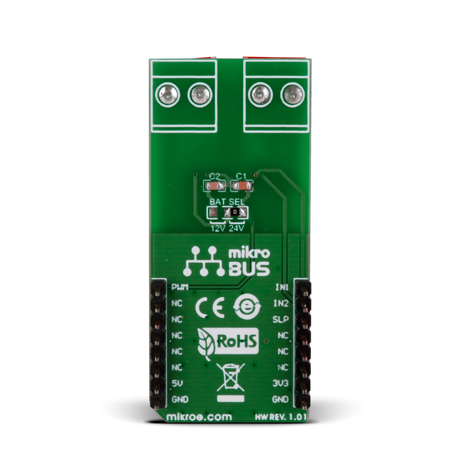
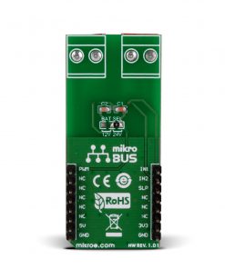
DC MOTOR 3 Click does not use the power for the TB6549FG or the connected motor from the mikroBUS™ socket. The right screw terminal powers the motor with a maximum supply voltage of 27V. The DC motor can be connected over the left screw terminal depending on the desired direction of the motor drive with a 2A max of output. At the bottom of the DC MOTOR 3 Click is a BAT SEL jumper to set the charge pump for driving the gate for the upper power transistor in the output circuit. On this Click board™, 24V is selected by default.
The only power this Click board™ will use from the mikroBUS™ socket is to power the PWR LED. This Click board™ comes equipped with a library containing easy-to-use functions and an example code that can be used, as a reference, for further development.
Specifications
Type
Brushed
Applications
Can be used for rapid development of various DC motor driving applications, including home appliances, printers, industrial equipment, mechatronic applications, and more
On-board modules
TB6549FG – full-bridge driver for direct current motors from Toshiba Semiconductor
Key Features
Drives motors up to 2A, full-bridge (CW, CCW, short brake, stop), built-in thermal shutdown circuit and overcurrent protection, PWM control capability, charge pump voltage selection, and more
Interface
GPIO,PWM
Feature
No ClickID
Compatibility
mikroBUS™
Click board size
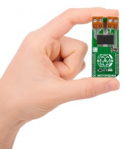
L (57.15 x 25.4 mm)
Input Voltage
3.3V,5V
Pinout diagram
This table shows how the pinout on DC MOTOR 3 Click corresponds to the pinout on the mikroBUS™ socket (the latter shown in the two middle columns).
Onboard settings and indicators
Label | Name | Default | Description |
---|---|---|---|
– | PWR | – | Power LED Indicator |
– | BAT SEL | Right | Charge Pump Selection 12V/24V: Left Position 12V, Right Position 24V |
DC MOTOR 3 Click electrical specifications
Description | Min | Typ | Max | Unit |
---|---|---|---|---|
Supply Voltage | 3.3 | – | 5 | V |
Power Supply Voltage | 10 | – | 27 | V |
Output Current | – | – | 2 | A |
Software Support
We provide a library for the DC Motor 3 Click as well as a demo application (example), developed using MIKROE compilers. The demo can run on all the main MIKROE development boards.
Package can be downloaded/installed directly from NECTO Studio Package Manager (recommended), downloaded from our LibStock™ or found on Mikroe github account.
Library Description
This library contains API for DC Motor 3 Click driver.
Key functions
-
This function set the direction of rotation in the clockwise direction by sets AN pin and clear RST pin.
-
This function set the direction of rotation in the counter clockwise direction by clear AN pin and sets RST pin.
-
This function brake the engine by sets AN and RST pins on DC Motor 3 Click board.
Example Description
This click has four operating modes: clockwise, counter-clockwise, short brake and stop. The operating mode is configured through IN1 and IN2 pins.
void application_task ( void )
{
log_printf( &logger, " Brake the engine rn" );
dcmotor3_short_brake( &dcmotor3 );
Delay_1sec();
log_printf( &logger, "---------------------rn" );
log_printf( &logger, " Clockwise rn" );
dcmotor3_clockwise( &dcmotor3 );
Delay_1sec();
for ( duty_cycle = 500; duty_cycle < dcmotor3.pwm_period; duty_cycle += 700 )
{
dcmotor3_set_duty_cycle ( &dcmotor3, duty_cycle );
log_printf( &logger, " >" );
Delay_1sec( );
}
log_printf( &logger, "rn" );
log_printf( &logger, "---------------------rn" );
log_printf( &logger, " Brake the engine rn" );
dcmotor3_short_brake( &dcmotor3 );
Delay_1sec( );
log_printf( &logger, "---------------------rn" );
log_printf( &logger, " Counter Clockwise rn" );
dcmotor3_counter_clockwise( &dcmotor3 );
Delay_1sec();
for ( duty_cycle = dcmotor3.pwm_period; duty_cycle > 500; duty_cycle -= 700 )
{
dcmotor3_set_duty_cycle ( &dcmotor3, duty_cycle );
log_printf( &logger, " <" );
Delay_1sec( );
}
log_printf( &logger, "rn" );
log_printf( &logger, "---------------------rn" );
dcmotor3_stop( &dcmotor3 );
Delay_1sec();
}
The full application code, and ready to use projects can be installed directly from NECTO Studio Package Manager (recommended), downloaded from our LibStock™ or found on Mikroe github account.
Other Mikroe Libraries used in the example:
- MikroSDK.Board
- MikroSDK.Log
- Click.DcMotor3
Additional notes and informations
Depending on the development board you are using, you may need USB UART click, USB UART 2 Click or RS232 Click to connect to your PC, for development systems with no UART to USB interface available on the board. UART terminal is available in all MIKROE compilers.
mikroSDK
This Click board™ is supported with mikroSDK – Mikroe Software Development Kit, that needs to be downloaded from the LibStock and installed for the compiler you are using to ensure proper operation of mikroSDK compliant Click board™ demo applications.
For more information about mikroSDK, visit the official page.