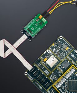
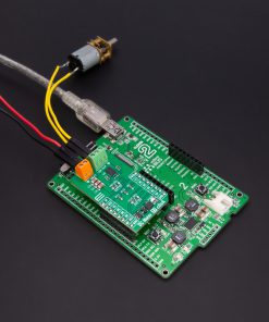
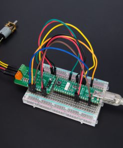
How does it work?
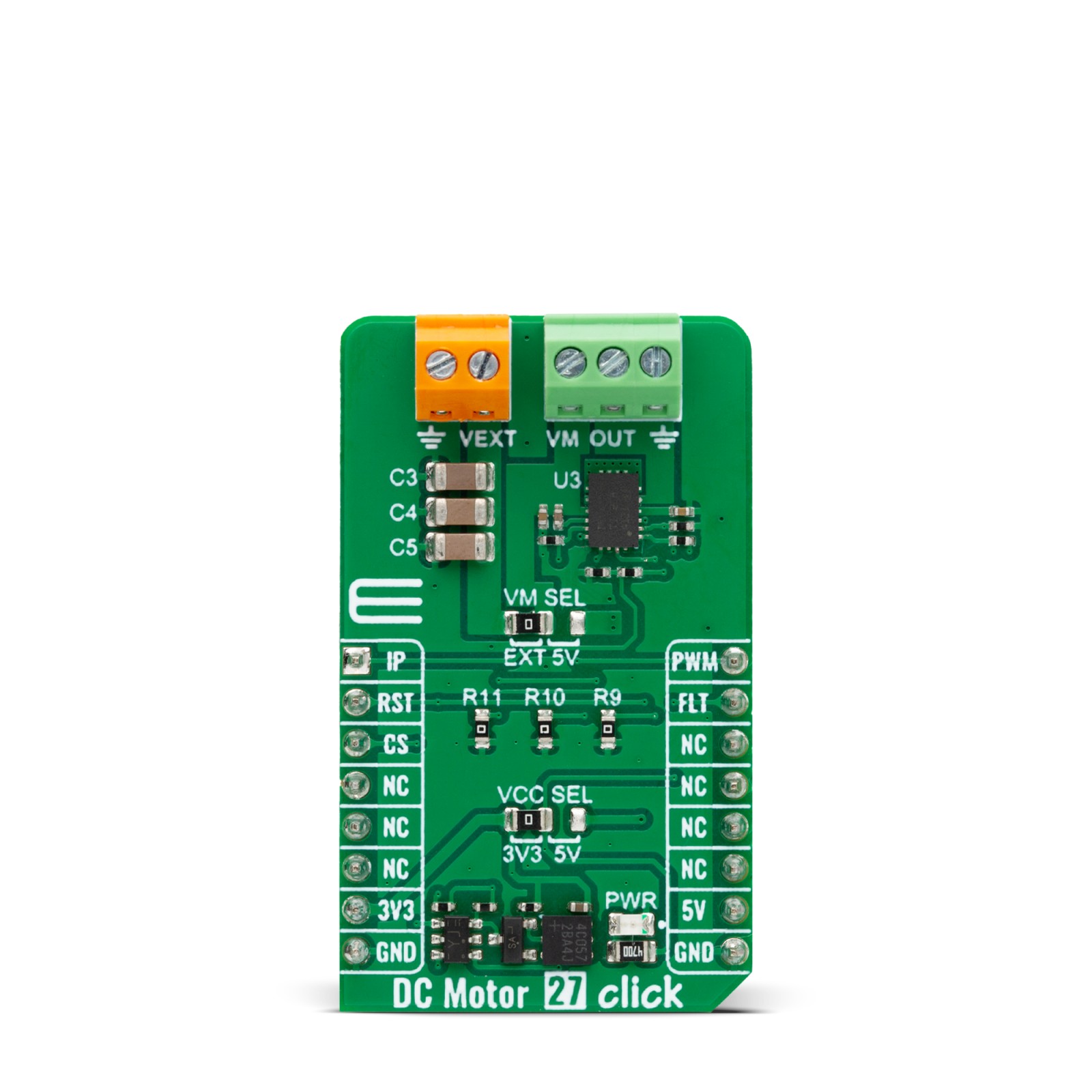
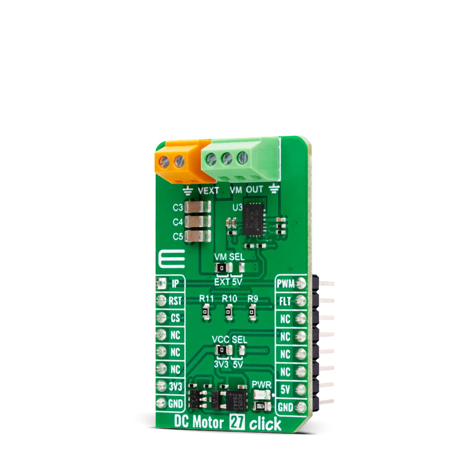
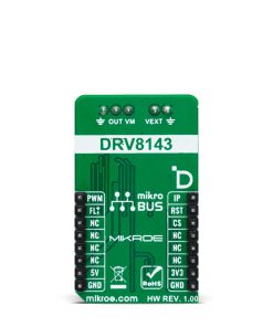
DC Motor 27 Click is based on the DRV8143, an automotive half-bridge driver with integrated current sense and diagnostic from Texas Instruments. The driver integrates an N-channel half-bridge charge pump regulator, high-side current sensing with regulation, current proportional output, and protection circuitry. It offers configurable current regulation, slew rate, spread spectrum clocking for low EMI, PWM frequency operation up to 125KHz with automatic dead time assertion, and more. The integrated current sense eliminates the need for a shunt resistor, and the driver supports a wide range of output currents for various types of motors and loads.
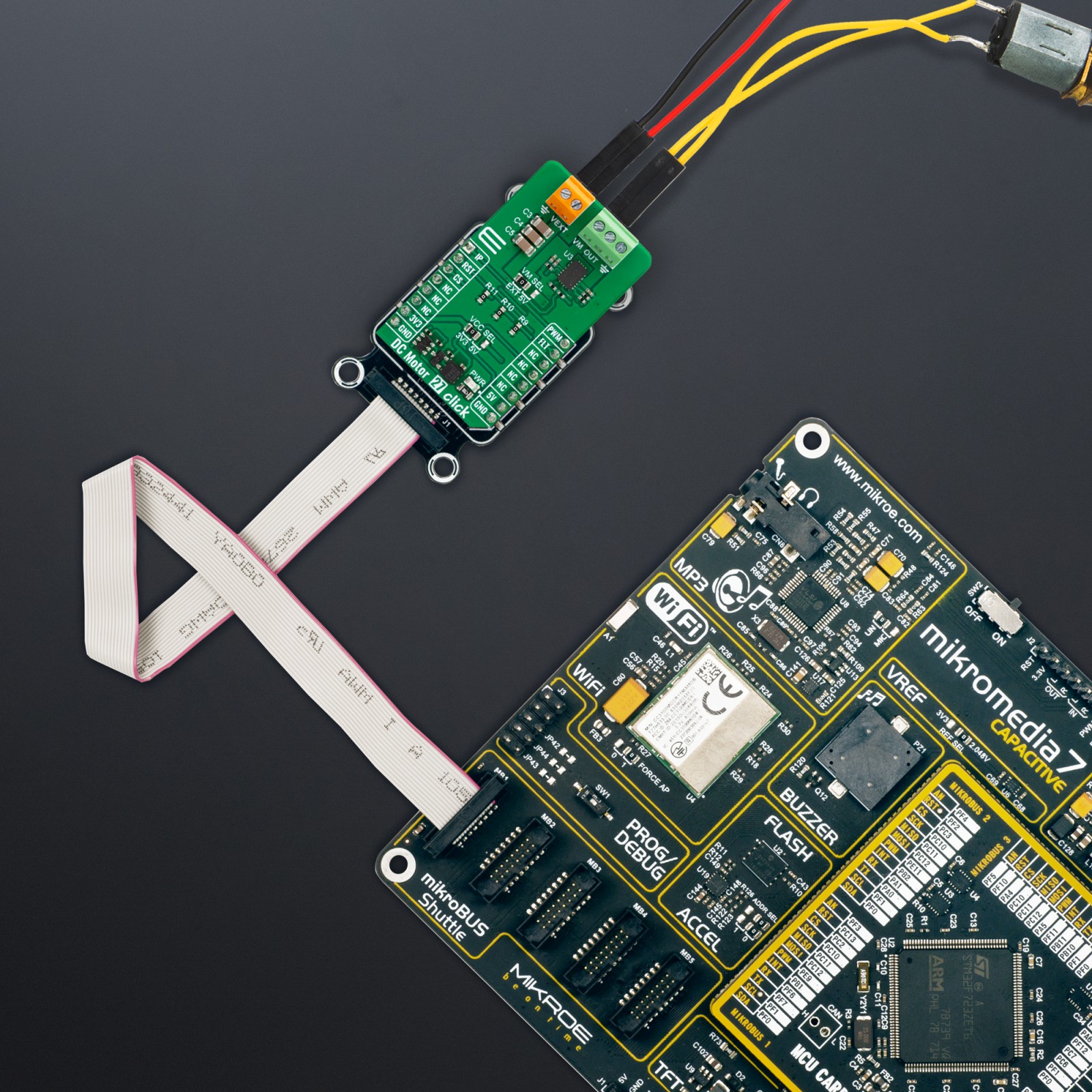
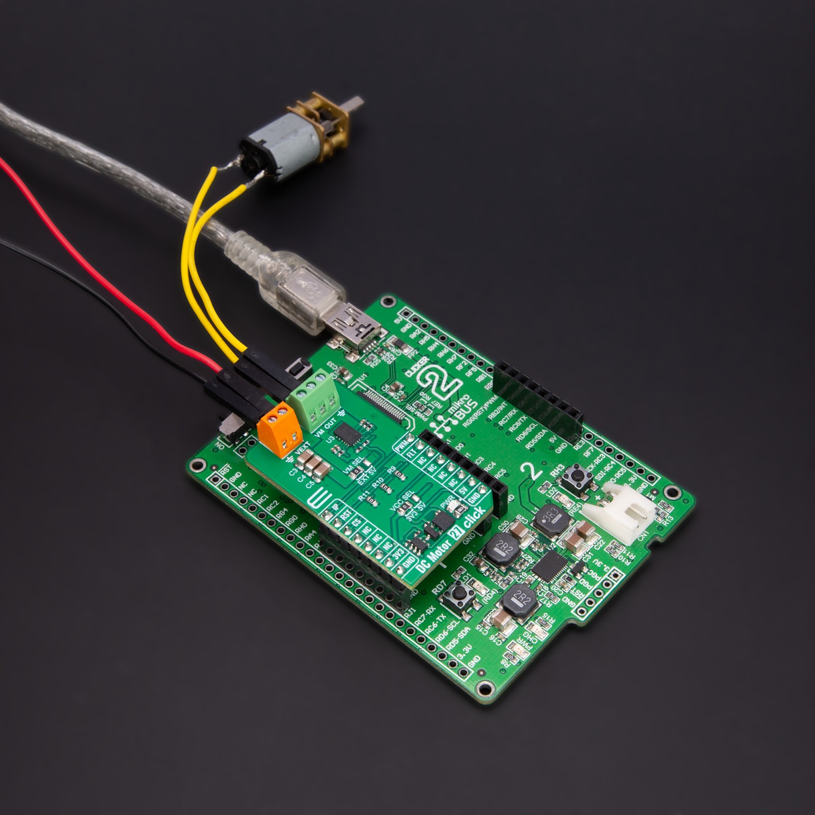
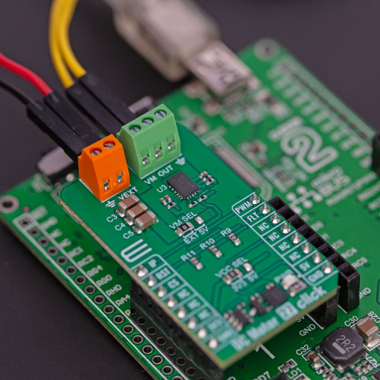
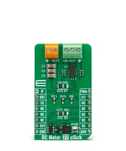
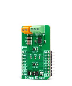
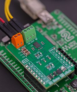
The device operates from a single power supply input (VM) available on the output terminal. The DC Motor 27 Click offers a VM SEL jumper that allows you to choose the power supply input from the external over the VEXT terminal and a 5V from the power rail of the mikroBUS™ socket. The EXT is set by default, so you should apply the appropriate voltage on the VEXT terminal.
DC Motor 27 Click uses a static pulse-width modulated (PWM) voltage signal to communicate with the host MCU, supporting either 100% or PWM drive modes. By resetting the driver over the RST pin, you are also turning OFF a controller input for bridge Hi-Z. You can always monitor the load current over the IP pin as an analog output of the driver. The driver uses the FLT pin to inform the host MCU of faults caused by load, overvoltage, and under-voltage on the VM pin.
This Click board™ can operate with either 3.3V or 5V logic voltage levels selected via the VCC SEL jumper. This way, both 3.3V and 5V capable MCUs can use the communication lines properly. Also, this Click board™ comes equipped with a library containing easy-to-use functions and an example code that can be used as a reference for further development.
Specifications
Type
Brushed
Applications
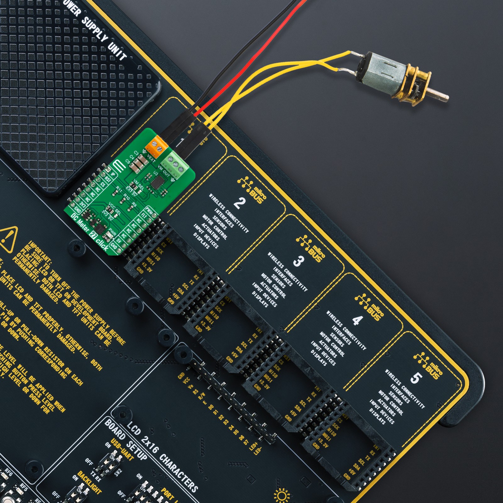
Can be used for the development of automotive brushed DC motors, solenoids, door modules, seat modules, body control modules (BCM), fuel, water, and oil pumps, onboard charger, and more
On-board modules
DRV8143 – half-bridge driver with integrated current sense and diagnostic from Texas Instruments
Key Features
Wide voltage operating range, PWM frequency operation up to 125KHz, configurable slew rate, integrated current sense, configurable current regulation, protection, and diagnostic features, and more
Interface
Analog,PWM
Feature
ClickID
Compatibility
mikroBUS™
Click board size
M (42.9 x 25.4 mm)
Input Voltage
3.3V or 5V
Pinout diagram
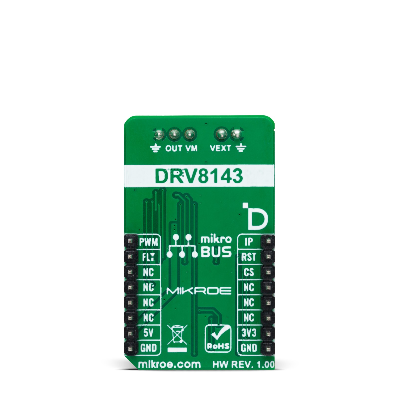
This table shows how the pinout on DC Motor 27 Click corresponds to the pinout on the mikroBUS™ socket (the latter shown in the two middle columns).
Onboard settings and indicators
Label | Name | Default | Description |
---|---|---|---|
LD1 | PWR | – | Power LED Indicator |
JP1 | VCC SEL | Left | Logic Level Voltage Selection 3V3/5V: Left position 3V3, Right position 5V |
JP2 | VM SEL | Left | DRV8143 Power Supply Selection EXT/5V: Left position EXT, Right position 5V |
DC Motor 27 Click electrical specifications
Description | Min | Typ | Max | Unit |
---|---|---|---|---|
Supply Voltage | 3.3 | – | 5 | V |
External Supply Voltage VM | 4.5 | – | 35 | V |
Maximum Output Current | – | – | 20 | A |
PWM Frequency | – | – | 125 | KHz |
Software Support
We provide a library for the DC Motor 27 Click as well as a demo application (example), developed using MIKROE compilers. The demo can run on all the main MIKROE development boards.
Package can be downloaded/installed directly from NECTO Studio Package Manager (recommended), downloaded from our LibStock™ or found on Mikroe github account.
Library Description
This library contains API for DC Motor 27 Click driver.
Key functions
-
dcmotor27_set_duty_cycle
DC Motor 27 sets PWM duty cycle. -
dcmotor27_get_flt_pin
DC Motor 27 get flt pin state. -
dcmotor27_set_coast
DC Motor 27 set coast mode funtion.
Example Description
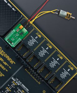
This example demonstrates the use of the DC Motor 27 Click board by driving the motor at different speeds, enabling brake and coast modes.
void application_task ( void )
{
for ( uint8_t speed_cnt = 10; speed_cnt <= 100; speed_cnt += 10 )
{
float speed = ( float ) speed_cnt / 100;
dcmotor27_set_duty_cycle( &dcmotor27, speed );
log_printf( &logger, " Motor speed %d%% rn", ( uint16_t ) speed_cnt );
Delay_ms( 1000 );
}
log_printf( &logger, " Motor coasting rn" );
dcmotor27_set_coast( &dcmotor27, DCMOTOR27_SET_COAST_ON );
Delay_ms( 2000 );
dcmotor27_set_coast( &dcmotor27, DCMOTOR27_SET_COAST_OFF );
for ( uint8_t speed_cnt = 10; speed_cnt <= 100; speed_cnt += 10 )
{
float speed = ( float ) speed_cnt / 100;
dcmotor27_set_duty_cycle( &dcmotor27, speed );
log_printf( &logger, " Motor speed %d%% rn", ( uint16_t ) speed_cnt );
Delay_ms( 1000 );
}
log_printf( &logger, " Motor brake is on rn" );
dcmotor27_pwm_stop( &dcmotor27 );
Delay_ms( 2000 );
dcmotor27_pwm_start( &dcmotor27 );
}
The full application code, and ready to use projects can be installed directly from NECTO Studio Package Manager (recommended), downloaded from our LibStock™ or found on Mikroe github account.
Other Mikroe Libraries used in the example:
- MikroSDK.Board
- MikroSDK.Log
- Click.DCMotor27
Additional notes and informations
Depending on the development board you are using, you may need USB UART click, USB UART 2 Click or RS232 Click to connect to your PC, for development systems with no UART to USB interface available on the board. UART terminal is available in all MIKROE compilers.
mikroSDK
This Click board™ is supported with mikroSDK – MIKROE Software Development Kit. To ensure proper operation of mikroSDK compliant Click board™ demo applications, mikroSDK should be downloaded from the LibStock and installed for the compiler you are using.
For more information about mikroSDK, visit the official page.