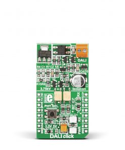
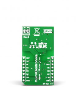
DALI Click
R545.00 ex. VAT
DALI Click is a compact add-on board that provides a Digital Addressable Lighting Interface (DALI) with any MCU. This board features two PS2701-1 small outline couplers capable of 3.75kV isolation from Renesas. DALI interface represents an industry-standardized protocol specified in the multi-part international standard IEC 62386. Equipped with a linear voltage regulator, a transmit/receive, and constant current circuits, this Click board™ has all the necessary parts to meet the DALI specifications. This Click board™ makes the perfect solution for intelligent digital lighting control and enables easy implementation of robust and flexible lighting networks.
DALI Click is supported by a mikroSDK compliant library, which includes functions that simplify software development. This Click board™ comes as a fully tested product, ready to be used on a system equipped with the mikroBUS™ socket.
Stock: Lead-time applicable.
| 5+ | R517.75 |
| 10+ | R490.50 |
| 15+ | R463.25 |
| 20+ | R445.81 |
How does it work?
DALI Click is based on the two PS2701-1 small outline couplers from Renesas. The DALI interface represents an international standardized protocol for intelligent lighting control. It offers a very flexible network routing topology, as all nodes can be daisy-chained, connected in a star topology, or any combination of these. The master and the slave nodes are connected to the DALI bus, where a single DALI network can control up to 64 lighting devices. Data between the host MCU and the devices are transferred over a two-wire bi-directional bus through an asynchronous, half-duplex serial protocol, regardless of polarity.
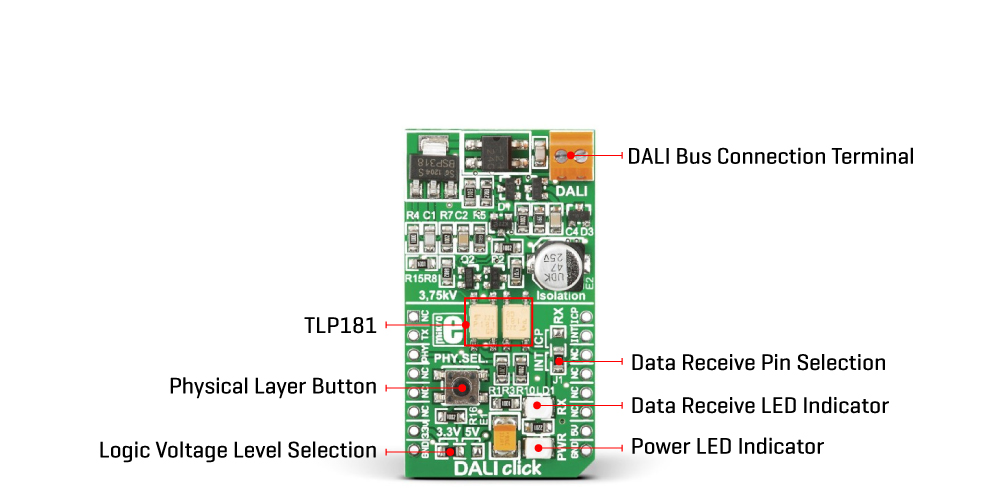
After optoisolation, the transmit circuit on DALI Click uses a FET, the BSP3185, to sink the total DALI power supply current so that the line can be pulled LOW with its capacitors limiting the rise/fall rates. The pulses are produced by not pulling the line LOW so that it goes HIGH due to the power supply. On the other hand, the receiving circuit allows a constant current in the range of voltages used for the high logic state representation. It should be noted that this circuit does not represent a current supply to the DALI bus.
According to the DALI standard, this Click board™ also has a built-in Graetz bridge rectifier on its DALI bus, which can be connected to the built-in screw terminal, marked as DALI regardless of signal polarity. After it has been rectified, the DALI TX and RX signals go through the fast optocouplers and remain galvanically isolated from the rest of the circuit. The TX signal is routed to the RST pin of the mikroBUS™ socket, while the RX signal, with its respective LED indicator, is routed over an onboard INT ICP jumper to the interrupt INT or input capture ICP (PWM) pins, with the INT pin as the default. The PHY SEL button, connected to the CS pin of the mikroBUS™ socket, can be used for the physical layer selection method documented in the Ed-1 version of the standard.
This Click board™ can operate with both 3.3V and 5V logic voltage levels selected via an onboard jumper. This way, it is allowed for both 3.3V and 5V capable MCUs to use the communication lines properly. However, the Click board™ comes equipped with a library containing easy-to-use functions and an example code that can be used, as a reference, for further development.
Specifications
Type
DALI
Applications
Can be used for controlling network based systems that controls lighting in buildings
On-board modules
PS2701-1 – small outline couplers from Renesas
Key Features
Compliant with the latest DALI standard revisions, control up to 64 lighting devices, data transfer over a two-wire bi-directional bus, all necessary onboard electronics according to the DALI standard, physical layer selection button, receive LED indicator, and more
Interface
GPIO
Feature
No ClickID
Compatibility
mikroBUS™
Click board size
M (42.9 x 25.4 mm)
Input Voltage
3.3V or 5V
Pinout diagram
This table shows how the pinout on DALI Click corresponds to the pinout on the mikroBUS™ socket (the latter shown in the two middle columns).
| Notes | Pin | Pin | Notes | ||||
|---|---|---|---|---|---|---|---|
| NC | 1 | AN | PWM | 16 | ICP | DALI RX | |
| DALI TX | TX | 2 | RST | INT | 15 | INT | DALI RX |
| SPI Chip Select | PHY | 3 | CS | RX | 14 | NC | |
| NC | 4 | SCK | TX | 13 | NC | ||
| NC | 5 | MISO | SCL | 12 | NC | ||
| NC | 6 | MOSI | SDA | 11 | NC | ||
| Power Supply | 3.3V | 7 | 3.3V | 5V | 10 | 5V | Power Supply |
| Ground | GND | 8 | GND | GND | 9 | GND | Ground |
Onboard settings and indicators
| Label | Name | Default | Description |
|---|---|---|---|
| LD1 | PWR | – | Power LED Indicator |
| J1 | INT ICP | Down | Communication Interface Selection INT/ICP RX: Down position INT RX, Up position ICP RX |
| J2 | – | Left | Logic Level Voltage Selection 3V3/5V: Left position 3V3, Right position 5V |
| T1 | PHY.SEL. | – | Physical Layer Selection Button |
DALI Click electrical specifications
| Description | Min | Typ | Max | Unit |
|---|---|---|---|---|
| Supply Voltage | 3.3 | – | 5 | V |
| DALI Voltage Range | 0 | – | 24 | V |
Resources
Downloads
| Weight | 30 g |
|---|---|
| Brand | MikroElektronika |