Current Sens Click
R1,350.00 ex. VAT
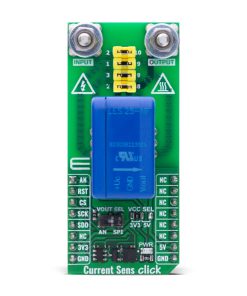
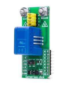
Current Sens Click is a compact add-on board for precise AC, DC, and pulsed current measurement with galvanic isolation. This board features the LES 25-NP current transducer from LEM USA, a closed-loop, multi-range sensor designed for accurate current detection up to 25A. The board offers selectable analog or digital output via SPI using the MCP3201 12-bit ADC, with a stable 2.5V reference provided by the MCP1525. A jumper-configurable section allows adjustment of the nominal primary current with support for three connection configurations to enhance resolution. It supports both 3.3V and 5V logic levels and includes an onboard switch for easy output selection. Ideal for industrial applications, it fits seamlessly into systems such as motor drives, UPS units, SMPS, battery-powered devices, welding equipment, and solar inverters.
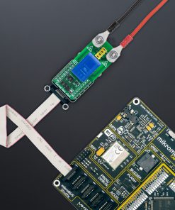
Current Sens Click is fully compatible with the mikroBUS™ socket and can be used on any host system supporting the mikroBUS™ standard. It comes with the mikroSDK open-source libraries, offering unparalleled flexibility for evaluation and customization. What sets this Click board™ apart is the groundbreaking ClickID feature, enabling your host system to seamlessly and automatically detect and identify this add-on board.
Stock: Lead-time applicable.
| 5+ | R1,282.50 |
| 10+ | R1,215.00 |
| 15+ | R1,147.50 |
| 20+ | R1,104.30 |
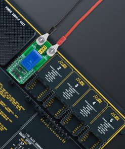
 DO NOT TOUCH THE BOARD WHILE THE EXTERNAL POWER SUPPLY IS ON!
Note: This Click board™ needs to be used by trained personnel only while applying high voltages. Special care should be taken when working with hazardous voltage levels.
How does it work?
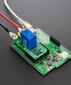
Current Sens Click is based on the LES 25-NP current transducer from LEM USA, a closed-loop, multi-range sensor capable of accurately detecting direct, alternating, and pulsed currents up to 25A. This device ensures galvanic isolation between the primary and secondary circuits, providing robust electrical safety and signal integrity. The LES 25-NP supports selectable output modes – either analog or digital – allowing for flexible integration into a wide range of systems. It operates on a unipolar DC supply voltage, simplifying power design requirements. With extremely low offset drift and strong immunity to rapid voltage transients (dv/dt), this sensor maintains reliable and consistent measurements even in electrically noisy environments. Engineered in compliance with multiple international safety and performance standards, including IEC 61800, IEC 62109, IEC 62477, and UL 508, Current Sens Click is well-suited for use in AC variable speed drives, servo motor controllers, DC motor converters, battery-powered systems, UPS units, SMPS units, welding equipment, and solar inverter solutions.

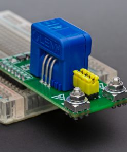
Just above the current sensor on the board, there is a dedicated jumper section that allows adjustment of the nominal primary current. The LES 25-NP sensor supports three different primary connection configurations, enabling precise measurement of either the full, half, or one-third of the primary current, which significantly enhances resolution in low-current applications. Each conductor exhibits a primary resistance of 0.72mΩ. The datasheet provides a reference table that outlines how different jumper settings define the primary nominal RMS current and corresponding primary resistance, based on the selected number of primary turns.
As mentioned, the LES 25-NP’s output signal can be converted to a digital value using MCP3201, a successive approximation A/D converter with a 12-bit resolution from Microchip, using an SPI compatible interface, or sent directly to an analog pin of the mikroBUS™ socket labeled as AN. Selection can be performed via an onboard SMD switch labeled VOUT SEL, placing it in an appropriate position marked as AN or SPI. To provide the required reference voltage for accurate digital conversion, the MCP3201 A/D converter uses the MCP1525, a precision 2.5V voltage reference from Microchip. This ensures stable and consistent reference conditions, allowing the MCP3201 to deliver reliable 12-bit digital output when measuring the analog signal from the LES 25-NP sensor.
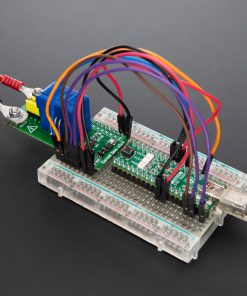
This Click board™ can operate with either 3.3V or 5V logic voltage levels selected via the VCC SEL jumper. This way, both 3.3V and 5V capable MCUs can use the communication lines properly. Also, this Click board™ comes equipped with a library containing easy-to-use functions and an example code that can be used as a reference for further development.
Specifications
Type
Current sensor
Applications
Ideal for industrial applications, it fits seamlessly into systems such as motor drives, UPS units, SMPS, battery-powered devices, welding equipment, and solar inverters
On-board modules
LES 25-NP – 25A current transducer from LEM USA
Key Features
Closed-loop multi-range current transducer, selectable analog or digital output via SPI, galvanic isolation between primary and secondary circuits, jumper-selectable nominal current configuration, low offset drift, high dv/dt immunity, unipolar supply operation, and more
Interface
Analog,SPI
Feature
ClickID
Compatibility
mikroBUS™
Click board size
L (57.15 x 25.4 mm)
Input Voltage
3.3V or 5V,External
Pinout diagram
This table shows how the pinout on Current Sens Click corresponds to the pinout on the mikroBUS™ socket (the latter shown in the two middle columns).
| Notes | Pin | Pin | Notes | ||||
|---|---|---|---|---|---|---|---|
| Analog Output | AN | 1 | AN | PWM | 16 | NC | |
| ID SEL | RST | 2 | RST | INT | 15 | NC | |
| SPI Select / ID COMM | CS | 3 | CS | RX | 14 | NC | |
| SPI Clock | SCK | 4 | SCK | TX | 13 | NC | |
| SPI Data OUT | SDO | 5 | MISO | SCL | 12 | NC | |
| NC | 6 | MOSI | SDA | 11 | NC | ||
| Power Supply | 3.3V | 7 | 3.3V | 5V | 10 | 5V | Power Supply |
| Ground | GND | 8 | GND | GND | 9 | GND | Ground |
Onboard settings and indicators
| Label | Name | Default | Description |
|---|---|---|---|
| LD1 | PWR | – | Power LED Indicator |
| JP1 | VCC SEL | Left | Power Supply Voltage Selection 3V3/5V: Left position 3V3, Right position 5V |
| SW1 | VOUT SEL | Right | Output A/D Voltage Selection AN/SPI: Left position AN, Right position SPI |
Current Sens Click electrical specifications
| Description | Min | Typ | Max | Unit |
|---|---|---|---|---|
| Supply Voltage | 3.3 | – | 5 | V |
| Primary Nominal RMS Current | – | 25 | – | A |
| Primary Resistance (per turn) | – | 0.72 | – | mΩ |
Software Support
Current Sens Click demo application is developed using the NECTO Studio, ensuring compatibility with mikroSDK‘s open-source libraries and tools. Designed for plug-and-play implementation and testing, the demo is fully compatible with all development, starter, and mikromedia boards featuring a mikroBUS™ socket.
Example Description
This example demonstrates the use of Current Sens Click board by reading and displaying the input current measurements.
Key Functions
currentsens_cfg_setupConfig Object Initialization function.currentsens_initInitialization function.currentsens_calib_offsetThis function calibrates the zero current offset value.currentsens_calib_resolutionThis function calibrates the data resolution at the known load current.currentsens_read_currentThis function reads the input current level [A].
Application Init
Initializes the driver and calibrates the zero current offset and data resolution at 3A load current.
Application Task
Reads the input current measurements and displays the results on the USB UART approximately once per second.
Application Output
This Click board can be interfaced and monitored in two ways:
- Application Output – Use the “Application Output” window in Debug mode for real-time data monitoring. Set it up properly by following this tutorial.
- UART Terminal – Monitor data via the UART Terminal using a USB to UART converter. For detailed instructions, check out this tutorial.
Additional Notes and Information
The complete application code and a ready-to-use project are available through the NECTO Studio Package Manager for direct installation in the NECTO Studio. The application code can also be found on the MIKROE GitHub account.
Resources
Downloads
| Weight | 32 g |
|---|---|
| Brand | MikroElektronika |