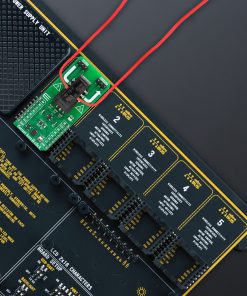
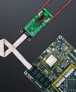
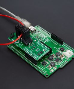
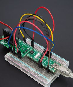
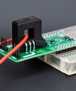
DO NOT TOUCH THE BOARD WHILE THE EXTERNAL POWER SUPPLY IS ON!
Note: This Click board™ needs to be used by trained personnel only while applying high voltages. Special care should be taken when working with hazardous voltage levels.
How does it work?
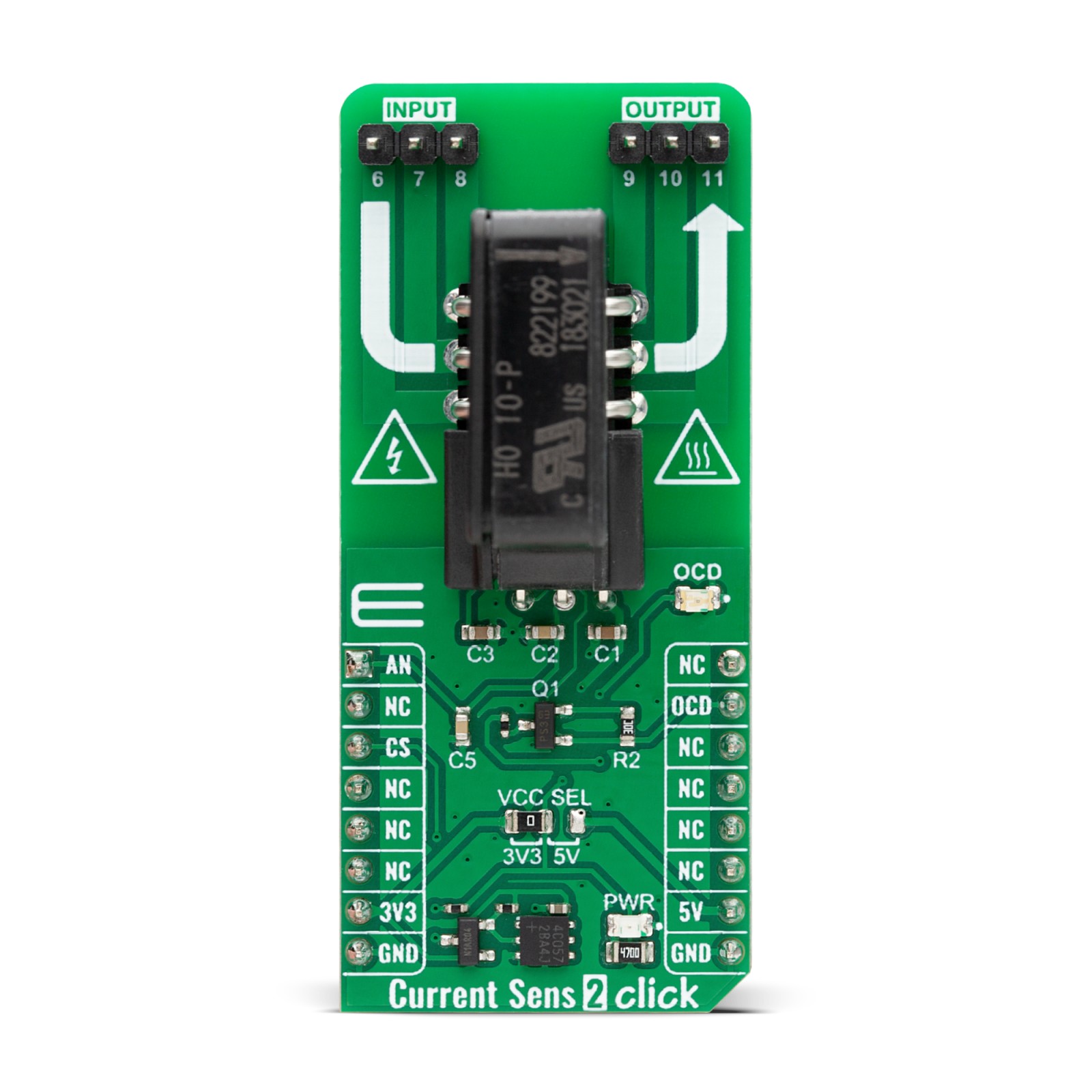
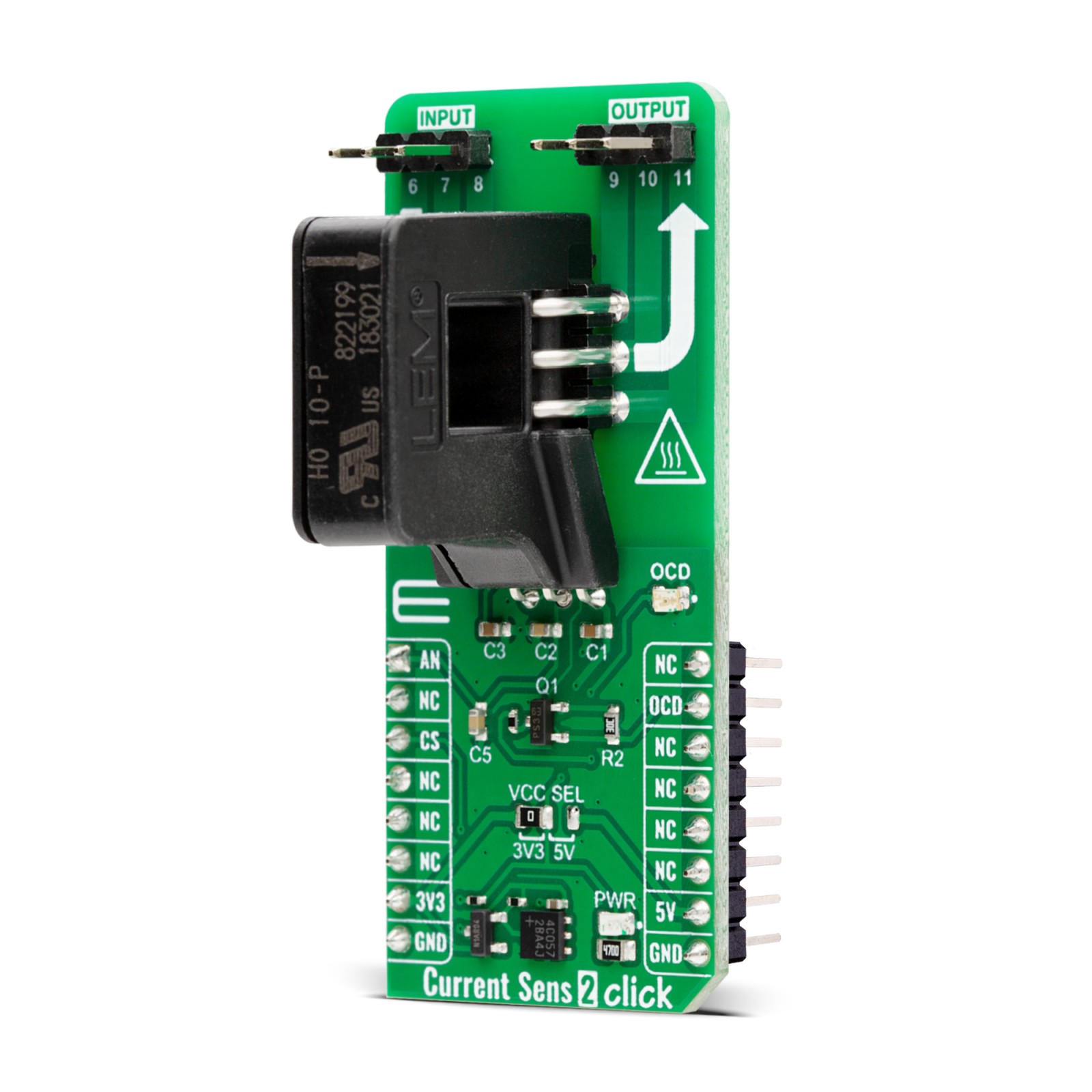
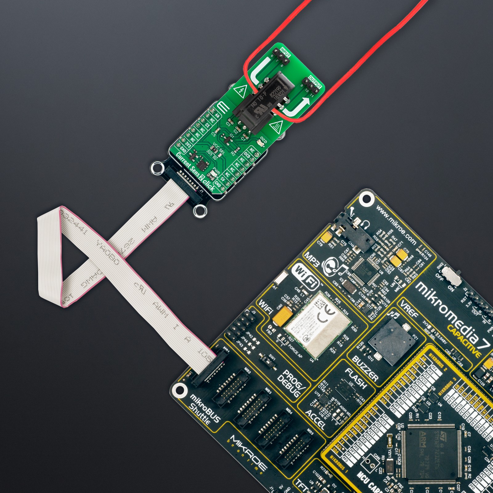
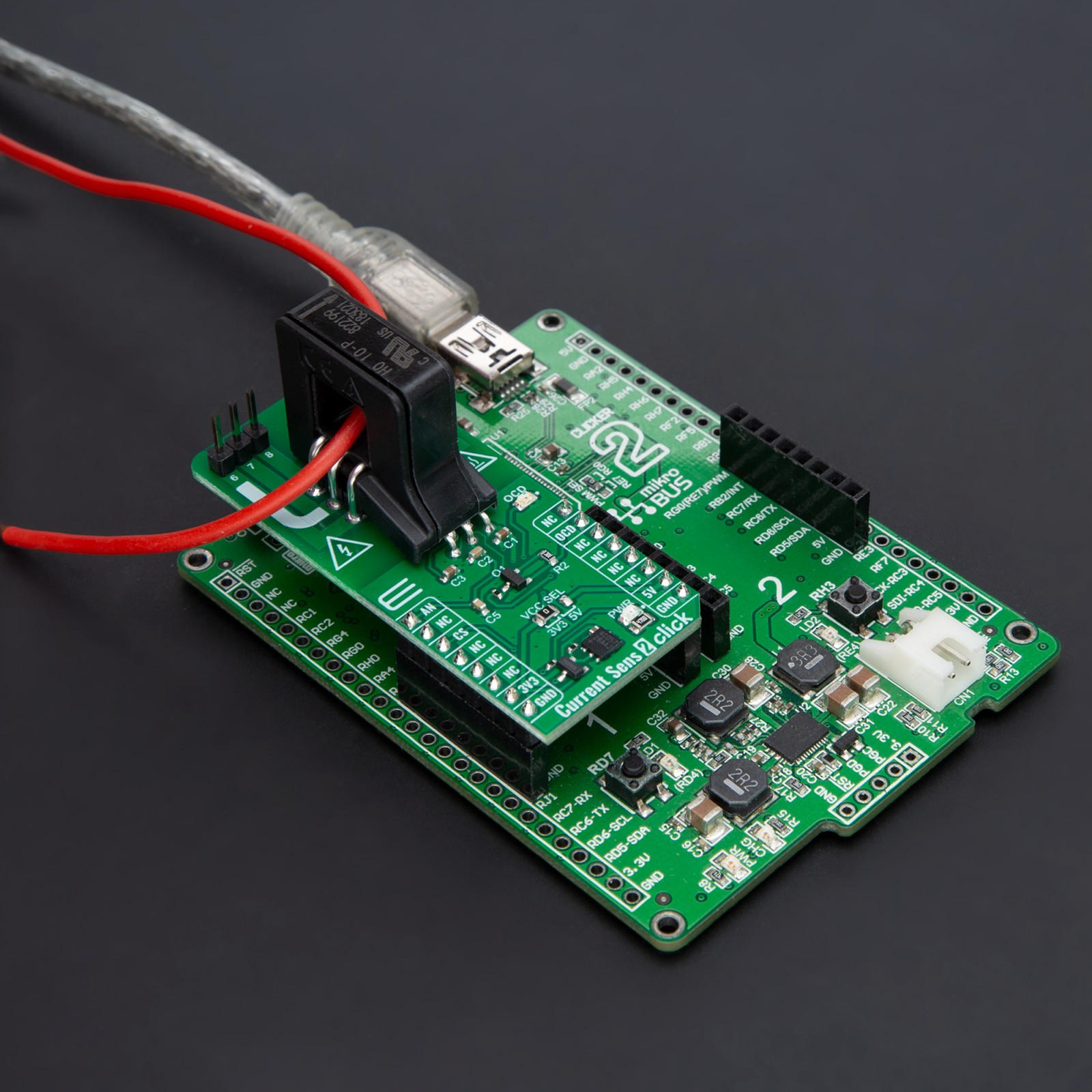
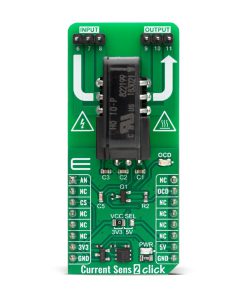
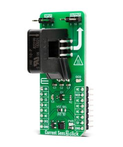
Current Sens 2 Click is based on the HO 10-P, an AC/DC current transducer from LEM USA. The HO 10-P is well-known for measuring DC, AC, and pulse currents up to 10ARMS with galvanic isolation between the primary and secondary circuits. With its core built on the open-loop Hall effect measuring principle, the Current Sens 2 Click ensures precise and reliable current measurements. Its capability covers a variety of industrial applications, including AC variable speed drives, UPS systems, SMPS, and power supplies for welding, which benefit from low power consumption and high immunity to external interference. The device’s fast response time suits dynamic and demanding environments.
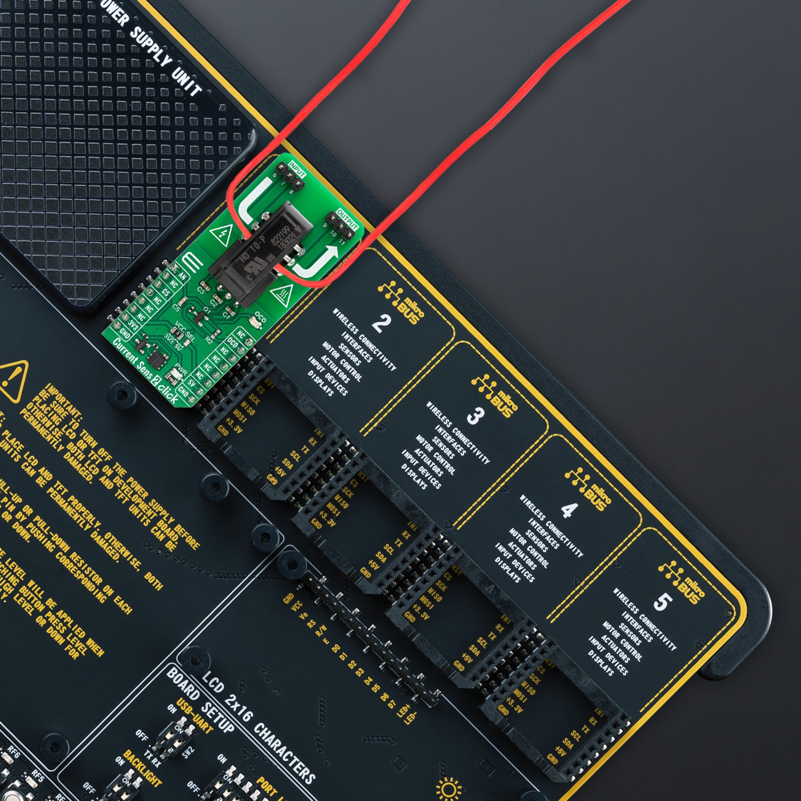
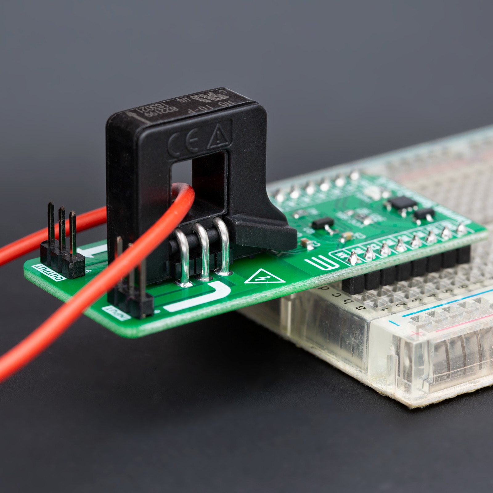
The HO 10-P is designed for through-hole PCB mounting and features a sizable aperture (8x8mm) for the primary conductor, ensuring easy integration and versatility. Although the sensor can measure current up to 10A, its sensitivity can be altered in three specific scenarios. When current is applied to the input, for instance, pin 6, and the output is obtained from pin 11, the sensor’s sensitivity becomes x1. This configuration is considered as the wire being wound only once around the sensor’s core, marking the first scenario.
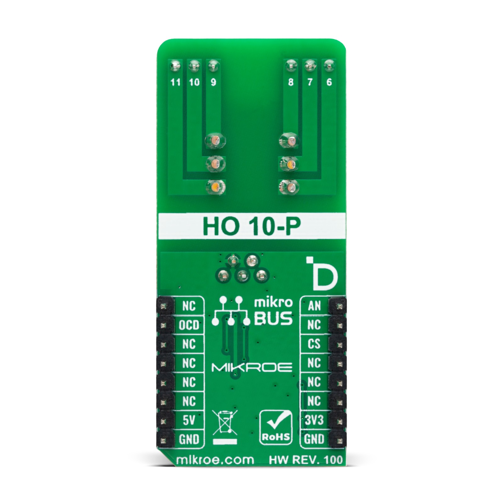
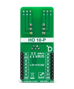
In another configuration, short-circuiting pins 7 and 10 while keeping the input and output on pins 6 and 11 doubles the sensitivity (x2). Similarly, sensitivity triples (x3) when pins 7-10 and 8-9 are short-circuited, maintaining the input and output on pins 6 and 11. Maintaining a straight signal path from the input to the output is crucial, as depicted in the schematic (6-11, 7-10, 8-9). It’s also possible to measure the conductor’s current by pulling it through the sensor’s core and allowing current to flow through it.
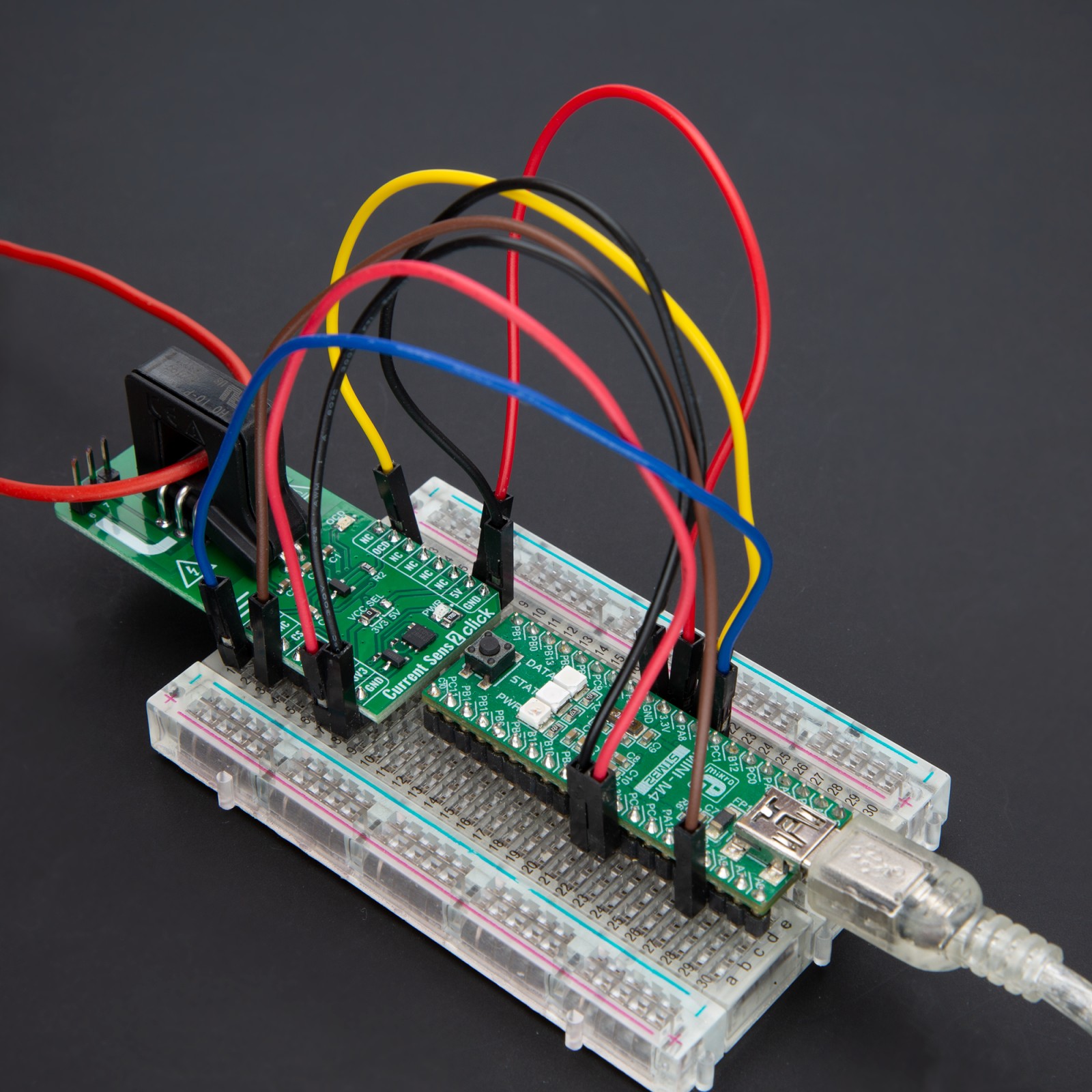
The sensor is powered by the 5V mikroBUS™ power rail and outputs the sensed current as an analog signal through the AN pin. Additionally, an orange LED and a dedicated pin (OCD) on the mikroBUS™ socket signal an overcurrent condition, providing enhanced safety and monitoring features.
This Click board™ can operate with either 3.3V or 5V logic voltage levels selected via the VCC SEL jumper. This way, both 3.3V and 5V capable MCUs can use the communication lines properly. Also, this Click board™ comes equipped with a library containing easy-to-use functions and an example code that can be used as a reference for further development.
Specifications
Type
Current sensor
Applications
Ideal for AC variable speed drives, UPS systems, SMPS, and power supplies for welding
On-board modules
HO 10-P – AC/DC current transducer from LEM USA
Key Features
Nominal RMS current up to 10A, AC/DC/pulse current measurement, sensitivity adjustments, galvanic isolation, open-loop Hall effect based, analog output, overcurrent detection, and more
Interface
Analog
Feature
ClickID
Compatibility
mikroBUS™
Click board size
L (57.15 x 25.4 mm)
Input Voltage
3.3V or 5V
Pinout diagram
This table shows how the pinout on Current Sens 2 Click corresponds to the pinout on the mikroBUS™ socket (the latter shown in the two middle columns).
Onboard settings and indicators
Label | Name | Default | Description |
---|---|---|---|
LD1 | PWR | – | Power LED Indicator |
LD2 | OCD | – | Overcurrent Detection LED Indicator |
JP1 | VCC SEL | Left | Logic Voltage Level Selection 3V3/5V: Left position 3V3, Right position 5V |
Current Sens 2 Click
Description | Min | Typ | Max | Unit |
---|---|---|---|---|
Supply Voltage | 3.3 | – | 5 | V |
Primary Nominal Current | – | 10 | – | Arms |
Sensitivity | – | 80 | – | mV/A |
Software Support
We provide a library for the Current Sens 2 Click as well as a demo application (example), developed using MikroElektronika compilers. The demo can run on all the main MikroElektronika development boards.
Package can be downloaded/installed directly from NECTO Studio Package Manager (recommended), downloaded from our LibStock™ or found on Mikroe github account.
Library Description
This library contains API for Current Sens 2 Click driver.
Key functions
-
currentsens2_get_int_pin
Current Sens 2 get int pin state function. -
currentsens2_tare
Current Sens 2 tare function. -
currentsens2_get_current
Current Sens 2 read current function.
Example Description
This example demonstrates the use of Current Sens 2 Click board™ by reading and displaying the input current measurements.
void application_task ( void )
{
float current = 0;
if ( CURRENTSENS2_OK == currentsens2_get_current ( ¤tsens2, ¤t ) )
{
log_printf( &logger, " Current : %.2f[A]rnn", current );
Delay_ms( 1000 );
}
}
The full application code, and ready to use projects can be installed directly from NECTO Studio Package Manager (recommended), downloaded from our LibStock™ or found on Mikroe github account.
Other Mikroe Libraries used in the example:
- MikroSDK.Board
- MikroSDK.Log
- Click.CurrentSens2
Additional notes and informations
Depending on the development board you are using, you may need USB UART click, USB UART 2 Click or RS232 Click to connect to your PC, for development systems with no UART to USB interface available on the board. UART terminal is available in all MikroElektronika compilers.
mikroSDK
This Click board™ is supported with mikroSDK – MikroElektronika Software Development Kit. To ensure proper operation of mikroSDK compliant Click board™ demo applications, mikroSDK should be downloaded from the LibStock and installed for the compiler you are using.
For more information about mikroSDK, visit the official page.