How does it work?
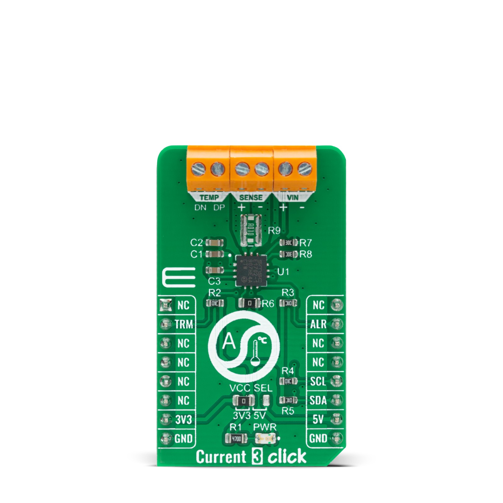
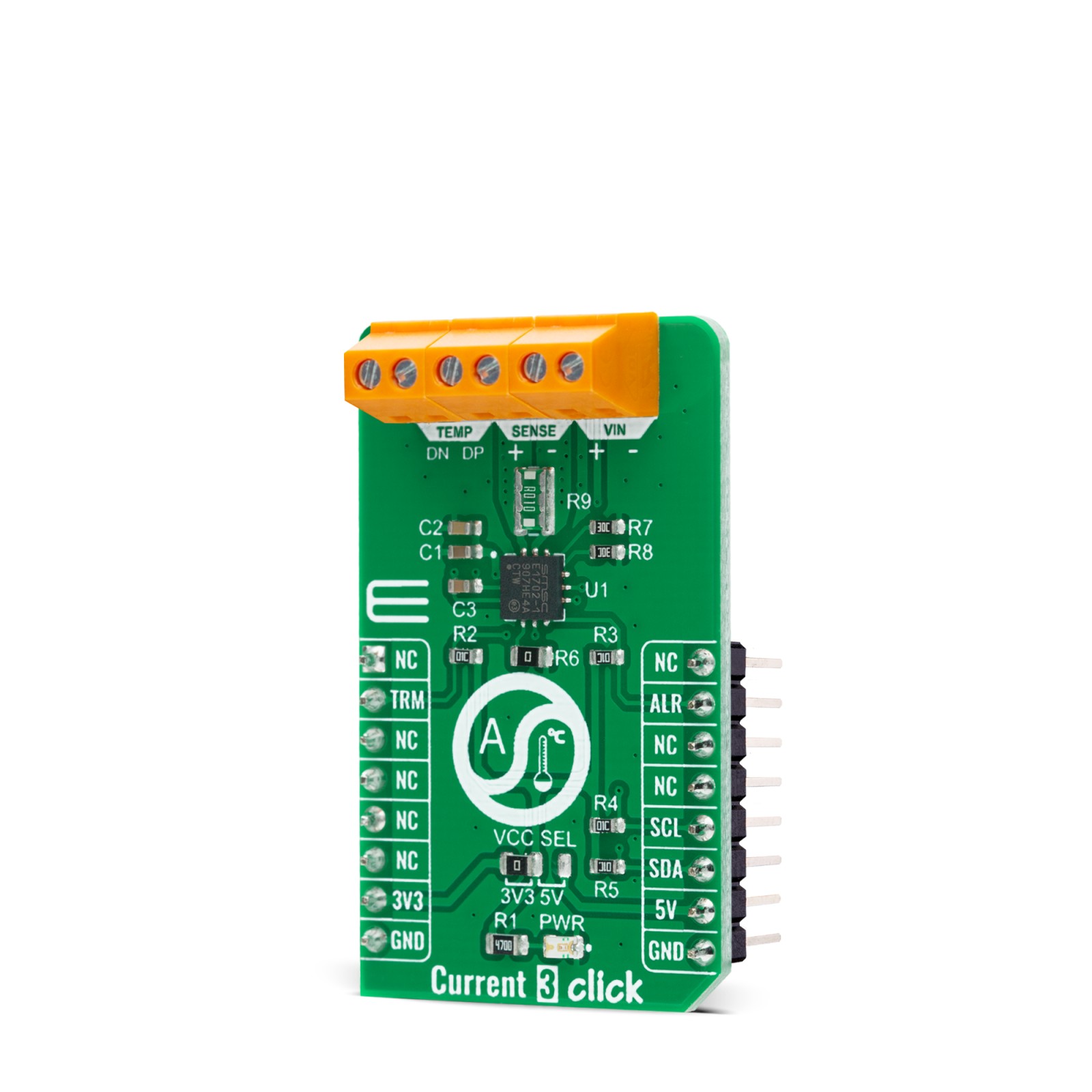
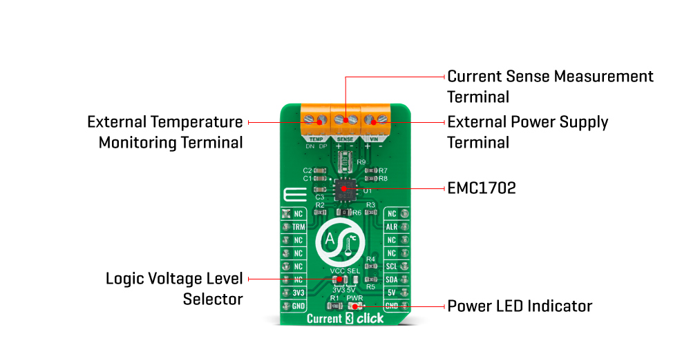
Current 3 Click is based on the EMC1702, a combination of the high-side current sensing device with a precision voltage and temperature measurement capabilities from Microchip. It measures the voltage developed across an external sense resistor to represent the high-side current of a battery or voltage regulator, and also measures the source voltage and uses these measured values to present a proportional power calculation. The EMC1702 contains additional bi-directional peak detection circuitry to flag instantaneous current spikes with programmable time duration and magnitude threshold. Also, it possesses an external diode channel for temperature measurement as well as an internal diode for ambient temperature measurements.
The EMC1702 current-sense measurement converts differential input voltage measured across an external sense resistor to a proportional output voltage. This voltage is digitized using a variable resolution (13-bit to 15-bit) Sigma-Delta ADC and I2C protocol. The current range allows for large variations in measured current with high accuracy and a low voltage drop across the resistor.
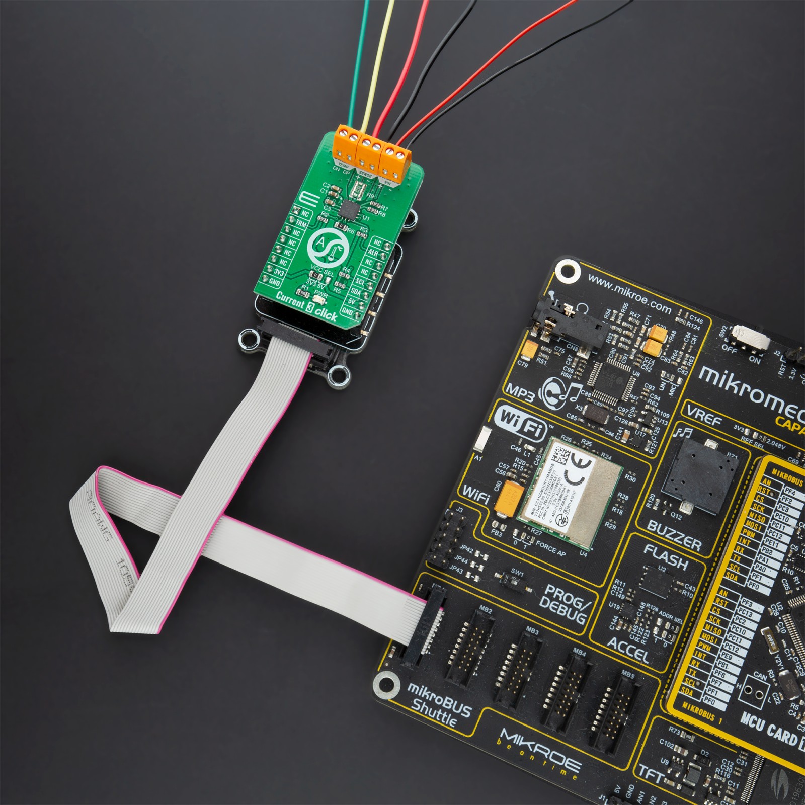
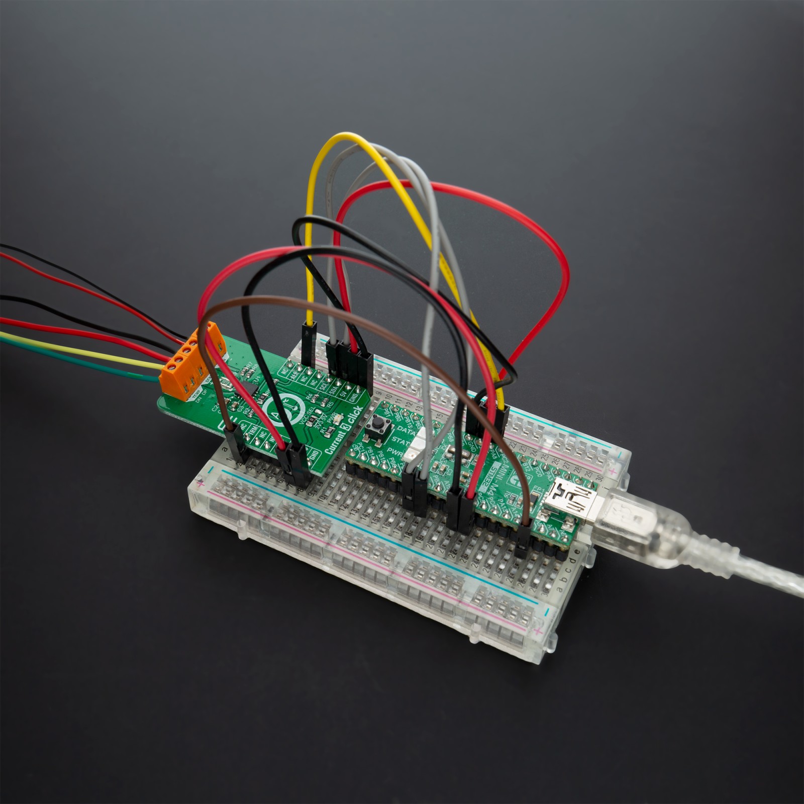
Current 3 Click communicates with MCU using the standard I2C 2-Wire interface with a maximum frequency of 400kHz. The EMC1702 slave address is determined by a resistor connected R6 (0Ω) between the ground and the ADDR_SEL pin. Various values of this resistor also provide different slave addresses (0Ω is equal to 1001_100(r/w)).
The EMC1702 has two levels of monitoring and contains user-programmable bipolar Full-Scale Sense Ranges (FSSR). Each VSENSE measurement is averaged over a user-programmable time. If VSENSE exceeds (or drops below) the respective limits, the ALERT pin, routed on the INT pin of the mikroBUS™ socket labeled as ALT, may be asserted. It also contains user-programmable current peak detection circuitry on DUR_SEL and TH_SEL pins that will assert the THERM pin, routed on the RST pin of the mikroBUS™ socket labeled as TRM, if a current spike is detected larger than the programmed threshold and of longer duration than the programmed time (threshold and duration selected by resistors R7 and R8).
This Click board™ is designed to be operated with both 3.3V and 5V logic voltage levels that can be selected via VCC SEL jumper. This allows for both 3.3V and 5V capable MCUs to use the I2C communication lines properly.
Specifications
Type
Current sensor,Measurements
Applications
Can be used for embedded, industrial, and power management systems applications.
On-board modules
Current 3 Click is based on the EMC1702, a combination of the high-side current sensing device with a precision voltage and temperature measurement capabilities from Microchip.
Key Features
High-side current sensor, temperature monitoring, hardware set peak detector, accuracy, and more.
Interface
I2C
Feature
No ClickID
Compatibility
mikroBUS™
Click board size
M (42.9 x 25.4 mm)
Input Voltage
3.3V or 5V
Pinout diagram
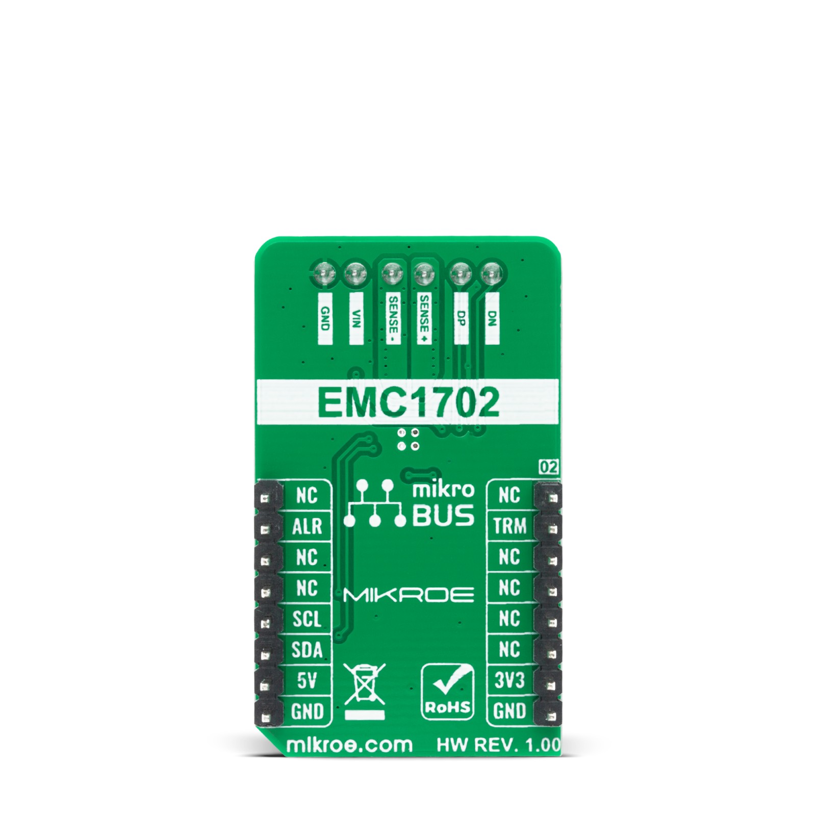
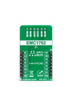
This table shows how the pinout on Current 3 Click corresponds to the pinout on the mikroBUS™ socket (the latter shown in the two middle columns).
Onboard settings and indicators
Label | Name | Default | Description |
---|---|---|---|
LD1 | PWR | – | Power LED Indicator |
JP1 | VCC SEL | Left | Logic Voltage Level Selection 3V3/5V: Left position 3V3, Right position 5V |
Current 3 Click electrical specifications
Description | Min | Typ | Max | Unit |
---|---|---|---|---|
Supply Voltage | -0.3 | – | 26 | V |
Voltage on SENSE terminal | -0.3 | – | 26 | V |
Peak Detector Threshold Range | – | 80 | – | mV |
Peak Detector Duration Range | – | 3072 | – | ms |
Operating Temperature Range | -40 | – | +85 | °C |
Software Support
We provide a library for the Current 3 Click on our LibStock page, as well as a demo application (example), developed using MikroElektronika compilers. The demo can run on all the main MikroElektronika development boards.
Library Description
The library covers all the necessary functions to control Current 3 Click board. A library performs the communication with the device via I2C interface.
Key functions:
float current3_get_temperature ( uint8_t temp_sel )
– Get temperature function.float current3_get_source_voltage ( void )
– Get source voltage function.float current3_get_current ( void )
– Get current measurement function.
Examples description
The application is composed of three sections :
- System Initialization – Initializes I2C and start to write log.
- Application Initialization – Initialization driver enables – I2C, check communication and set sense sampling configuration, also write log.
- Application Task – (code snippet) This is an example which demonstrates the use of Current 3 Click board. Current 3 Click board can be used to measure current ranging up to 8000mA, and display temperature, voltage and current data. All data logs write on USB uart changes for every 2 sec.
void application_task ( ) { temperature = current3_get_temperature( CURRENT3_TEMP_INTERNAL_DIODE ); FloatToStr( temperature, log_text ); Ltrim( log_text ); mikrobus_logWrite( " Temperature = ", _LOG_TEXT ); mikrobus_logWrite( log_text, _LOG_TEXT ); mikrobus_logWrite( " C", _LOG_LINE ); voltage = current3_get_source_voltage( ); FloatToStr( voltage, log_text ); Ltrim( log_text ); mikrobus_logWrite( " Voltage = ", _LOG_TEXT ); mikrobus_logWrite( log_text, _LOG_TEXT ); mikrobus_logWrite( " V", _LOG_LINE ); current = current3_get_current( ); FloatToStr( current, log_text ); mikrobus_logWrite( " Current = ", _LOG_TEXT ); mikrobus_logWrite( log_text, _LOG_TEXT ); mikrobus_logWrite( " mA", _LOG_LINE ); mikrobus_logWrite( "---------------------------", _LOG_LINE ); Delay_ms( 2000 ); }
The full application code, and ready to use projects can be found on our LibStock page.
Other mikroE Libraries used in the example:
- I2C
- UART
- Conversions
Additional notes and informations
Depending on the development board you are using, you may need USB UART click, USB UART 2 click or RS232 click to connect to your PC, for development systems with no UART to USB interface available on the board. The terminal available in all MikroElektronika compilers, or any other terminal application of your choice, can be used to read the message.
mikroSDK
This Click board™ is supported with mikroSDK – MikroElektronika Software Development Kit. To ensure proper operation of mikroSDK compliant Click board™ demo applications, mikroSDK should be downloaded from the LibStock and installed for the compiler you are using.
For more information about mikroSDK, visit the official page.