How does it work?
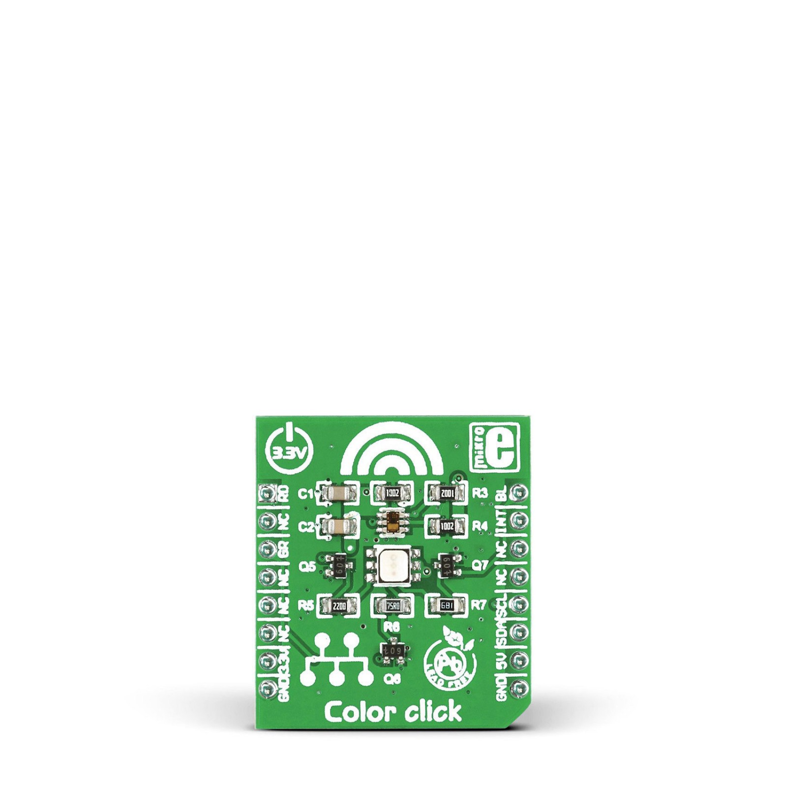
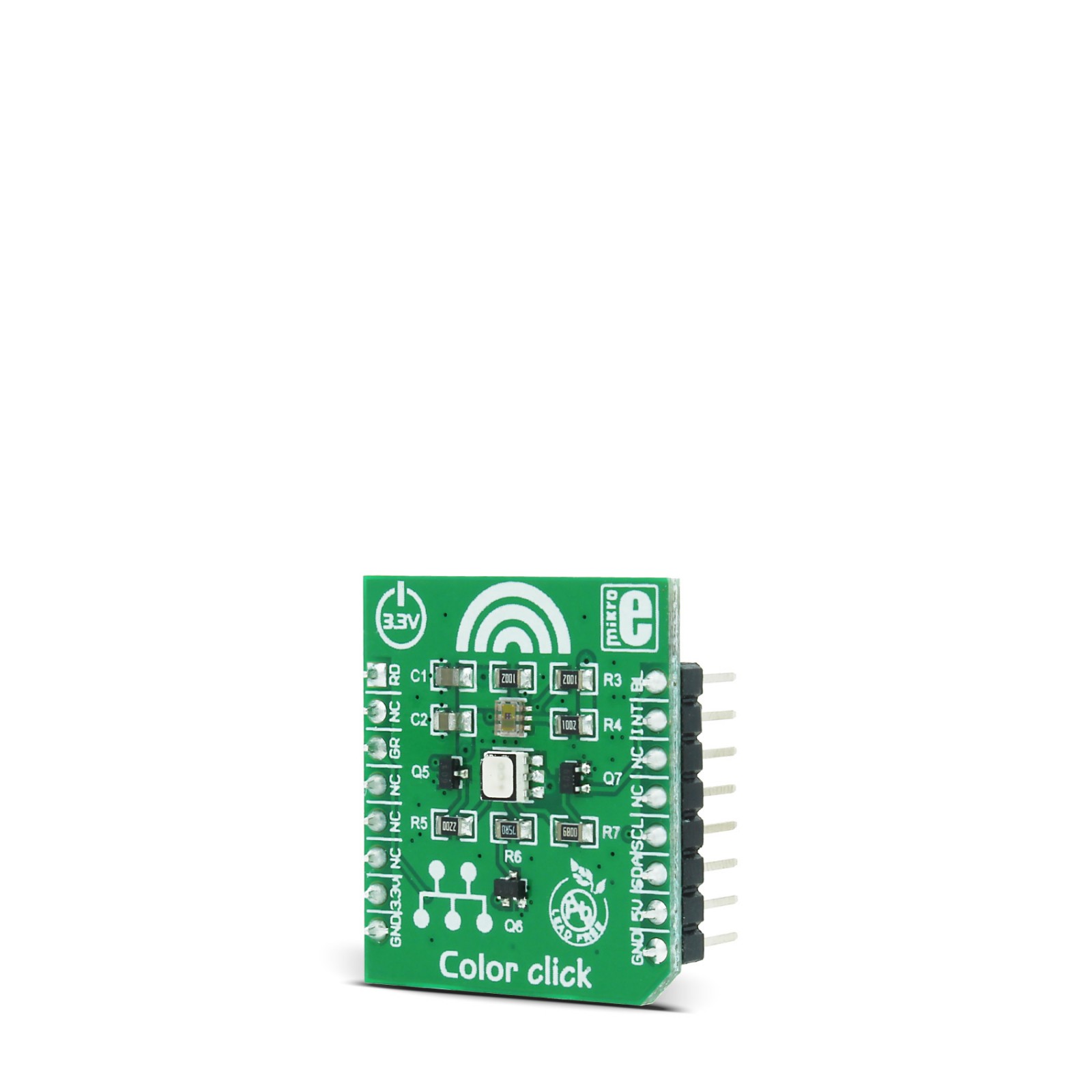
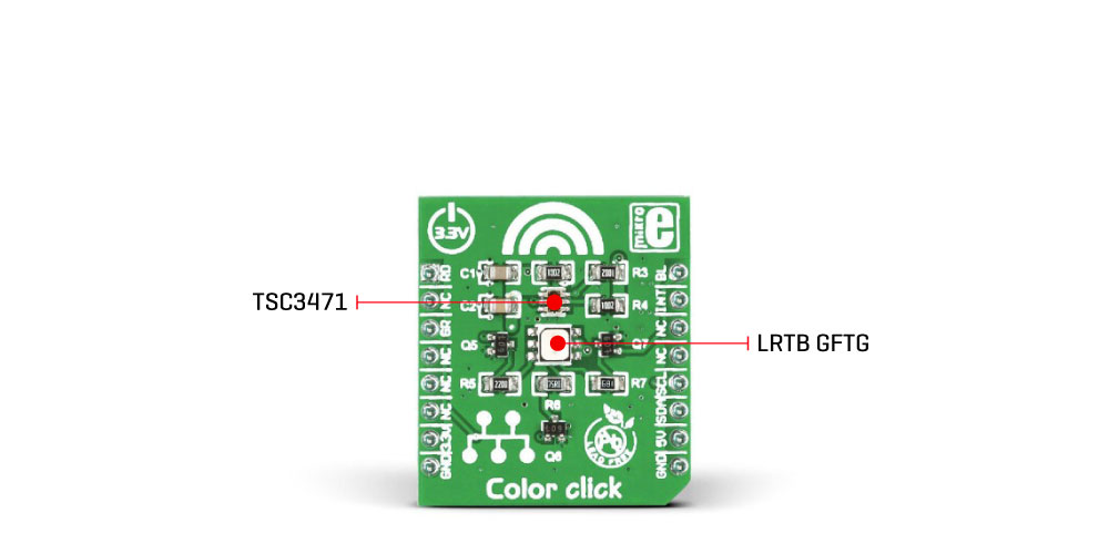
Color Click is based on the TCS3471, a color light-to-digital converter from ams AG. The TCS3471 color sensor features a 4×4 array of photo-diodes, which allow the detection of each light component: red, green, and blue (R, G, B). Additionally, it can sense the clear light component, too. The sensor IC has a programmable gain control (for all segments simultaneously), applying gain ratios of 1, 4, 16, and 60. The sensor has an integrating 16-bit ADC section for each channel, performing signal integration, which affects both the sensitivity and the acquisition time. The sensor has no IR filter; thus, it must be placed under the IR-blocking glass if sensing ambient light. However, it is ideally suited for RGB lighting applications since the LEDs emit light in reasonably narrow spectrum bands with no IR component. In such a scenario, the sensor can achieve a dynamic range of up to 1,000,000:1.
Color Click uses a standard 2-wire I2C interface to communicate with the host MCU supporting I2C fast mode with a clock frequency of up to 400kHz. The TCS3471 uses an interrupt INT pin to alert the MCU when a certain condition is reached. The ams AG RGB LED is controlled directly via the GPIO pins of the host microcontroller, the RD, GR, and BL pins. Instead of HIGH or LOW logic levels, bringing the PWM signal to these pins allows brightness control of the R, G, and B segments of the LRTB GFTG.
This Click board™ can operate with either 3.3V or 5V logic voltage levels selected via the PWR SEL jumper. This way, both 3.3V and 5V capable MCUs can use the communication lines properly. Also, this Click board™ comes equipped with a library containing easy-to-use functions and an example code that can be used as a reference for further development.
Specifications
Type
Color Sensing,Optical
Applications
an ideal solution for It can be used for the RGB LED color correction, backlight adjustment, in robotics – for the object color recognition, light color temperature sensing, and similar applications that require accurate and flexible color sensing
On-board modules
TCS3471 integrated color light-to-digital converter, by ams-TAOS; LRTB GFTG RGB LED from Osram
Key Features
High dynamic range, red, green, blue, and clear light detection, onboard RGB led for low light situations, fast I2C communication, buffered writes for increased data reliability, programmable interrupt engine, and more
Interface
GPIO,I2C
Feature
No ClickID
Compatibility
mikroBUS™
Click board size
S (28.6 x 25.4 mm)
Input Voltage
3.3V,5V
Pinout diagram
This table shows how the pinout on Color click corresponds to the pinout on the mikroBUS™ socket (the latter shown in the two middle columns).
Onboard settings and indicators
Label | Name | Default | Description |
---|---|---|---|
LD3A-LD3C | – | – | RGB LED |
Color Click electrical specifications
Description | Min | Typ | Max | Unit |
---|---|---|---|---|
Supply Voltage | 3.3 | – | 5 | V |
Spectral Response | 300 | – | 1000 | nm |
Peak Wavelength (R/G/B/C) | 710/850/810/760 | nm | ||
Resolution | – | – | 16 | bit |
Software Support
We provide a library for the Color Click as well as a demo application (example), developed using MIKROE compilers. The demo can run on all the main MIKROE development boards.
Package can be downloaded/installed directly from NECTO Studio Package Manager(recommended), downloaded from our LibStock™ or found on Mikroe github account.
Library Description
This library contains API for Color Click driver.
Key functions
-
This function reads desired color ratio from register.
-
This function reads 3 color filters and clear filters and converts the resulting color from RGBC to HSL.
-
This function determines which color is read by click sensor function has been invoked previously.
Example Description
The following code demonstrates color detection/recognition functionality of the click.
void application_task ( void )
{
color_value = color_get_color_value( &color );
is_color = color_get_color( color_value );
switch( is_color )
{
case ORANGE_COLOR_FLAG:
{
log_printf( &logger, "--- Color: ORANGErn" );
break;
}
case RED_COLOR_FLAG:
{
log_printf( &logger, "--- Color: REDrn" );
break;
}
case PINK_COLOR_FLAG:
{
log_printf( &logger, "--- Color: PINKrn" );
break;
}
case PURPLE_COLOR_FLAG:
{
log_printf( &logger, "--- Color: PURPLErn" );
break;
}
case BLUE_COLOR_FLAG:
{
log_printf( &logger, "--- Color: BLUErn" );
break;
}
case CYAN_COLOR_FLAG:
{
log_printf( &logger, "--- Color: CYANrn" );
break;
}
case GREEN_COLOR_FLAG:
{
log_printf( &logger, "--- Color: GREENrn" );
break;
}
case YELLOW_COLOR_FLAG:
{
log_printf( &logger, "--- Color: YELLOWrn" );
break;
}
default:
{
break;
}
}
Delay_ms( 300 );
}
The full application code, and ready to use projects can be installed directly from NECTO Studio Package Manager(recommended), downloaded from our LibStock™ or found on Mikroe github account.
Other Mikroe Libraries used in the example:
- MikroSDK.Board
- MikroSDK.Log
- Click.Color
Additional notes and informations
Depending on the development board you are using, you may need USB UART click, USB UART 2 Click or RS232 Click to connect to your PC, for development systems with no UART to USB interface available on the board. UART terminal is available in all MIKROE compilers.
mikroSDK
This Click board™ is supported with mikroSDK – MIKROE Software Development Kit. To ensure proper operation of mikroSDK compliant Click board™ demo applications, mikroSDK should be downloaded from the LibStock and installed for the compiler you are using.
For more information about mikroSDK, visit the official page.