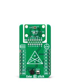

Color 19 Click
R270.00 ex. VAT
Color 19 Click is a compact add-on board for precise color and light intensity measurement. This board features the OPT4060, a high-speed, high-sensitivity RGBW color sensor from Texas Instruments. The OPT4060 features four channels with optimized spectral responses, including red, green, blue, and wide-band (white), ensuring accurate light intensity (lux) and color analysis across various lighting conditions. With flexible configuration options, including programmable light conversion times and impressive sensitivity down to 2.15mlux, this board adapts to diverse application requirements. The innovative Click Snap feature allows the sensor area to be detached and used autonomously for enhanced implementation flexibility. Color 19 Click is ideal for smart lighting, display color adjustment, ambient light sensing, and environmental monitoring applications.
Color 19 Click is fully compatible with the mikroBUS™ socket and can be used on any host system supporting the mikroBUS™ standard. It comes with the mikroSDK open-source libraries, offering unparalleled flexibility for evaluation and customization. What sets this Click board™ apart is the groundbreaking ClickID feature, enabling your host system to seamlessly and automatically detect and identify this add-on board, alongside a Click Snap feature introducing a new level of flexibility and ease of use.
Stock: Lead-time applicable.
| 5+ | R256.50 |
| 10+ | R243.00 |
| 15+ | R229.50 |
| 20+ | R220.86 |
How does it work?
Color 19 Click is based on the OPT4060, a high-speed, high-sensitivity RGBW color sensor from Texas Instruments, designed to measure color and light intensity with exceptional precision. This single-chip sensor is engineered for advanced color detection and can measure four channels: red, green, blue, and a wide-band (white) channel. Each channel features an optimized spectral response, enabling accurate color and light intensity analysis across various lighting conditions. This Click board™ delivers accurate light intensity (lux) and color data, making it suitable for smart lighting, display color adjustment, ambient light sensing, and environmental monitoring applications.

The OPT4060 incorporates specialized optical filters with finely tuned spectral responses for the RGB channels. This ensures strong rejection of wavelengths outside their target range, particularly in the near-infrared (NIR) spectrum at 850 and 940nm. This ensures reliable measurements in environments where NIR interference is prevalent. Additionally, its wide-band channel provides comprehensive light intensity data, allowing for precise lux calculations and color characterization.
The OPT4060 also provides flexible configuration options, with light conversion times ranging from 600μs to 800ms across 12 programmable steps per channel. This adaptability allows the sensor to meet various application requirements, balancing speed and resolution based on the user’s needs. The sensor achieves impressive sensitivity and can detect light levels as low as 2.15mlux, making it ideal for applications requiring precise light-level monitoring in both low and high-illumination environments.
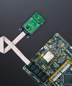
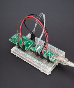
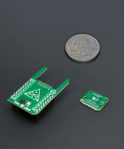
This Click board™ is designed in a unique format supporting the newly introduced MIKROE feature called “Click Snap.” Unlike the standardized version of Click boards, this feature allows the main sensor area to become movable by breaking the PCB, opening up many new possibilities for implementation. Thanks to the Snap feature, the OPT4060 can operate autonomously by accessing its signals directly on the pins marked 1-8. Additionally, the Snap part includes a specified and fixed screw hole position, enabling users to secure the Snap board in their desired location.
Color 19 Click uses an I2C interface with clock speeds of up to 2.6MHz, ensuring fast communication with the host MCU. The I2C address can be easily configured via onboard jumper ADDR SEL in the Snap area, allowing multiple devices to coexist on the same bus. Beyond communication pins, this board is also equipped with an interrupt (INT) pin that enables the host to MCU to sleep or ignore the sensor results until a user-defined event occurs (whether the light is above or below interest levels).
This Click board™ can be operated only with a 3.3V logic voltage level. The board must perform appropriate logic voltage level conversion before using MCUs with different logic levels. It also comes equipped with a library containing functions and example code that can be used as a reference for further development.
Click Snap
Click Snap is an innovative feature of our standardized Click add-on boards, introducing a new level of flexibility and ease of use. This feature allows for easy detachment of the main sensor area by simply snapping the PCB along designated lines, enabling various implementation possibilities. For detailed information about Click Snap, please visit the official page dedicated to this feature.
Specifications
Type
Color Sensing,Optical
Applications
Ideal for smart lighting, display color adjustment, ambient light sensing, and environmental monitoring applications
On-board modules
OPT4060 – RGBW color sensor from Texas Instruments
Key Features
High speed, high sensitivity, Red, Green, Blue, and Wide-band channels with optimized spectral responses, infrared rejection, configurable light conversion times, I2C interface, Click Snap, interrupt, and more
Interface
I2C
Feature
Click Snap,ClickID
Compatibility
mikroBUS™
Click board size
L (57.15 x 25.4 mm)
Input Voltage
3.3V
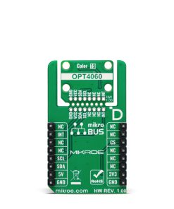
Pinout diagram
This table shows how the pinout on Color 19 Click corresponds to the pinout on the mikroBUS™ socket (the latter shown in the two middle columns).
| Notes | Pin | Pin | Notes | ||||
|---|---|---|---|---|---|---|---|
| NC | 1 | AN | PWM | 16 | NC | ||
| NC | 2 | RST | INT | 15 | INT | Interrupt | |
| ID COMM | CS | 3 | CS | RX | 14 | NC | |
| NC | 4 | SCK | TX | 13 | NC | ||
| NC | 5 | MISO | SCL | 12 | SCL | I2C Clock | |
| NC | 6 | MOSI | SDA | 11 | SDA | I2C Data | |
| Power Supply | 3.3V | 7 | 3.3V | 5V | 10 | NC | |
| Ground | GND | 8 | GND | GND | 9 | GND | Ground |
Onboard settings and indicators
| Label | Name | Default | Description |
|---|---|---|---|
| LD1 | PWR | – | Power LED Indicator |
| JP1 | ADDR SEL | Left | I2C Address Selection 0/1: Left position 0, Right position 1 |
Color 19 Click electrical specifications
| Description | Min | Typ | Max | Unit |
|---|---|---|---|---|
| Supply Voltage | – | 3.3 | – | V |
| Peak Spectral Responsivity (R/G/B/W) | 605/555/450/500 | nm | ||
| ADC Resolution | 9 | – | 20 | bits |
Software Support
Color 19 Click demo application is developed using the NECTO Studio, ensuring compatibility with mikroSDK‘s open-source libraries and tools. Designed for plug-and-play implementation and testing, the demo is fully compatible with all development, starter, and mikromedia boards featuring a mikroBUS™ socket.
Example Description
This example demonstrates the use of Color 19 Click by reading and displaying the color measurement from RGBW channels and the light intensity level in lux.
Key Functions
color19_cfg_setupConfig Object Initialization function.color19_initInitialization function.color19_default_cfgClick Default Configuration function.color19_get_int_pinThis function returns the INT pin logic state.color19_read_dataThis function reads the color data measurement of all channels and calculates the light intensity in lux.color19_check_communicationThis function checks the communication by reading and verifying the device ID.
Application Init
Initializes the driver and performs the Click default configuration.
Application Task
Waits for a data ready interrupt then reads the color measurement from RGBW channels and the light intensity level in lux and displays the results on the USB UART every 200ms approximately.
Application Output
This Click board can be interfaced and monitored in two ways:
- Application Output – Use the “Application Output” window in Debug mode for real-time data monitoring. Set it up properly by following this tutorial.
- UART Terminal – Monitor data via the UART Terminal using a USB to UART converter. For detailed instructions, check out this tutorial.
Additional Notes and Information
The complete application code and a ready-to-use project are available through the NECTO Studio Package Manager for direct installation in the NECTO Studio. The application code can also be found on the MIKROE GitHub account.
Resources
Downloads
| Weight | 17 g |
|---|---|
| Brand | MikroElektronika |