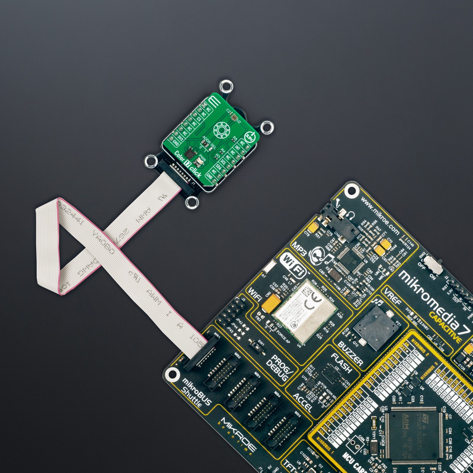
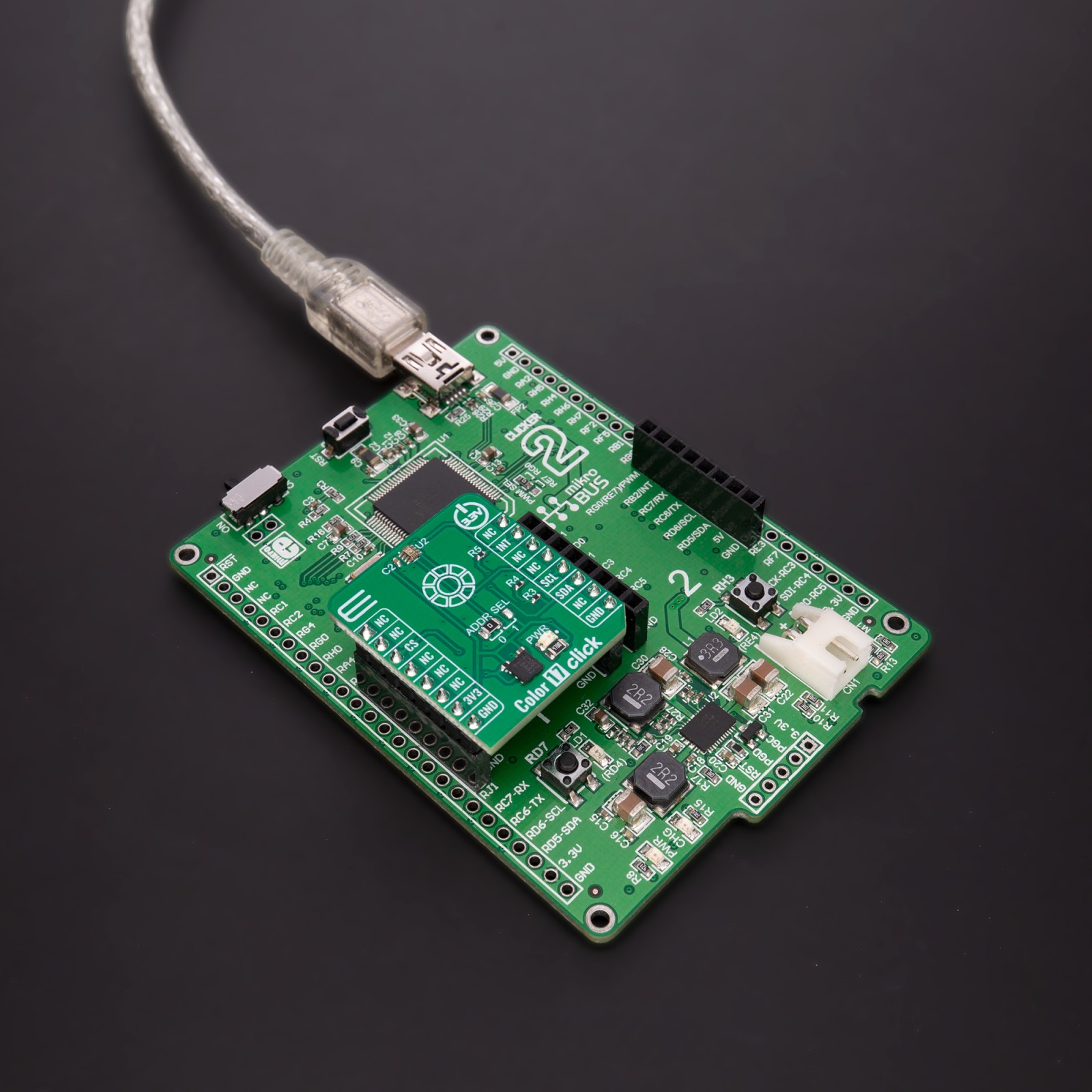
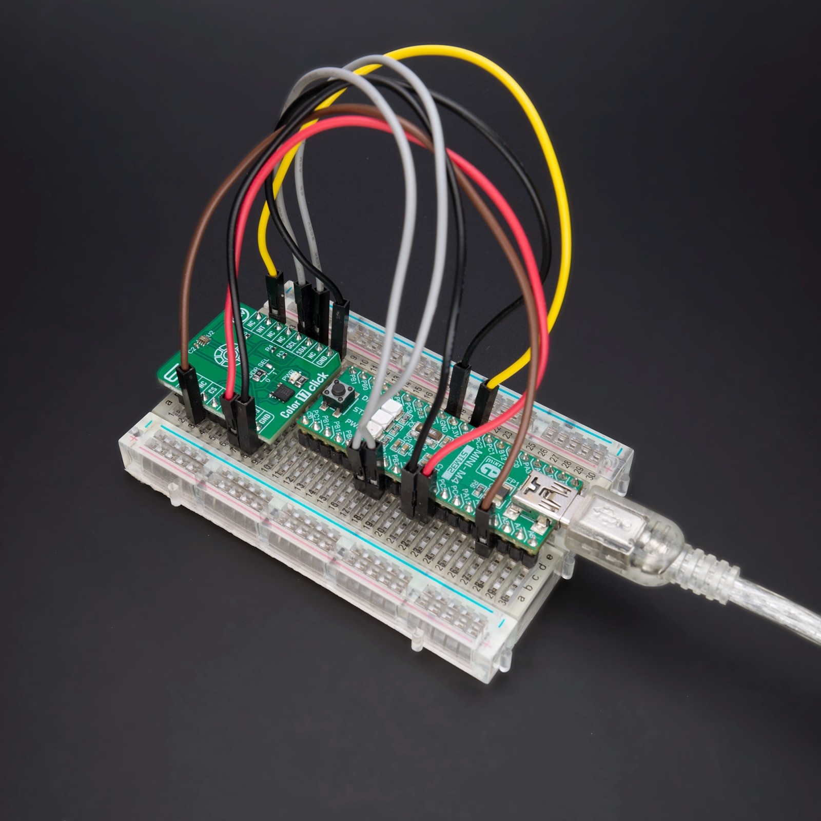
How does it work?
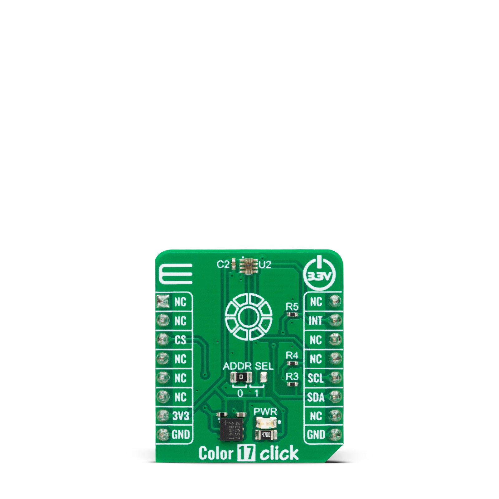
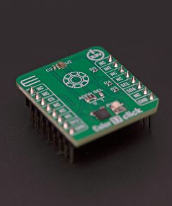
Color 17 Click is based on the OPT4048, a high-speed precision tristimulus XYZ color sensor from Texas Instruments, designed to mimic the human eye’s normal vision. The human eye has spectral sensitivity in a range of short, middle, and long wavelengths but in a correlation with a range of brightness. The CIE XYZ color space represents all color sensations visible to an average human eye, where the X is a mix of the three CIE RGB curves, the Y is the illuminance, and the Z is a quasi-equal to blue, according to the CIE 1931 model. The CIE XYZ is fixed color space, and one must note that there is a difference between the objects that emits light (and color) and objects that reflect light (and color). To put it more clearly, the monitor you look at and the wall behind it.
The OPT4048 has three channels closely matching the CIE tristimulus spectra and a fourth with a wide-band spectral response. Measures from these channels give us the characteristics of the lighting environment, such as the light intensity, color, LUV coordinates, and correlated color temperature. While closely mimicking the human eye, the OPT4084 rejects the wavelengths from their peaks, especially the NIR region (infrared) that the human eye does not see, which is a crucial part of this sensor.
To achieve excellent filter performance even at higher angles of light incidence, the OPT4084 uses advanced filter technology, high-resolution color measurements, and built-in automatic full-scale light range selection logic. By default, the OPT4048 is configured to operate in an automatic full-scale range detection mode that always selects the best full-scale range setting for the given lighting conditions. There are seven full-scale range settings, one of which can also be selected manually. Setting the device to operate in automatic full-scale range detection mode frees the user from having to program their software for potential iterative cycles of measurement and readjustment of the full-scale range until good for any given measurement. It also shows excellent linearity over the entire 26-bit dynamic range of measurement from 2.15mlux up to 144klux, with a highly linear response within each range.
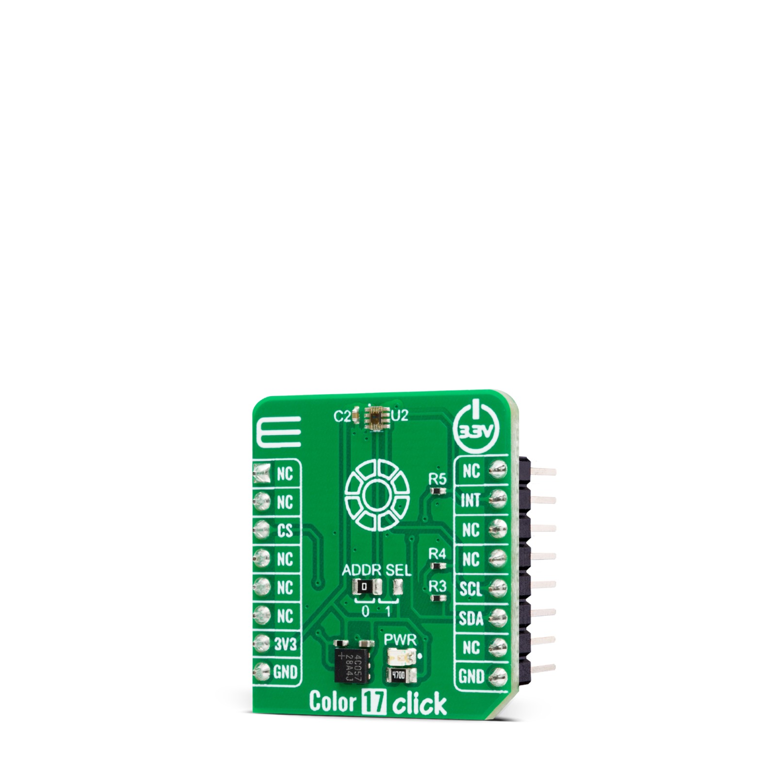
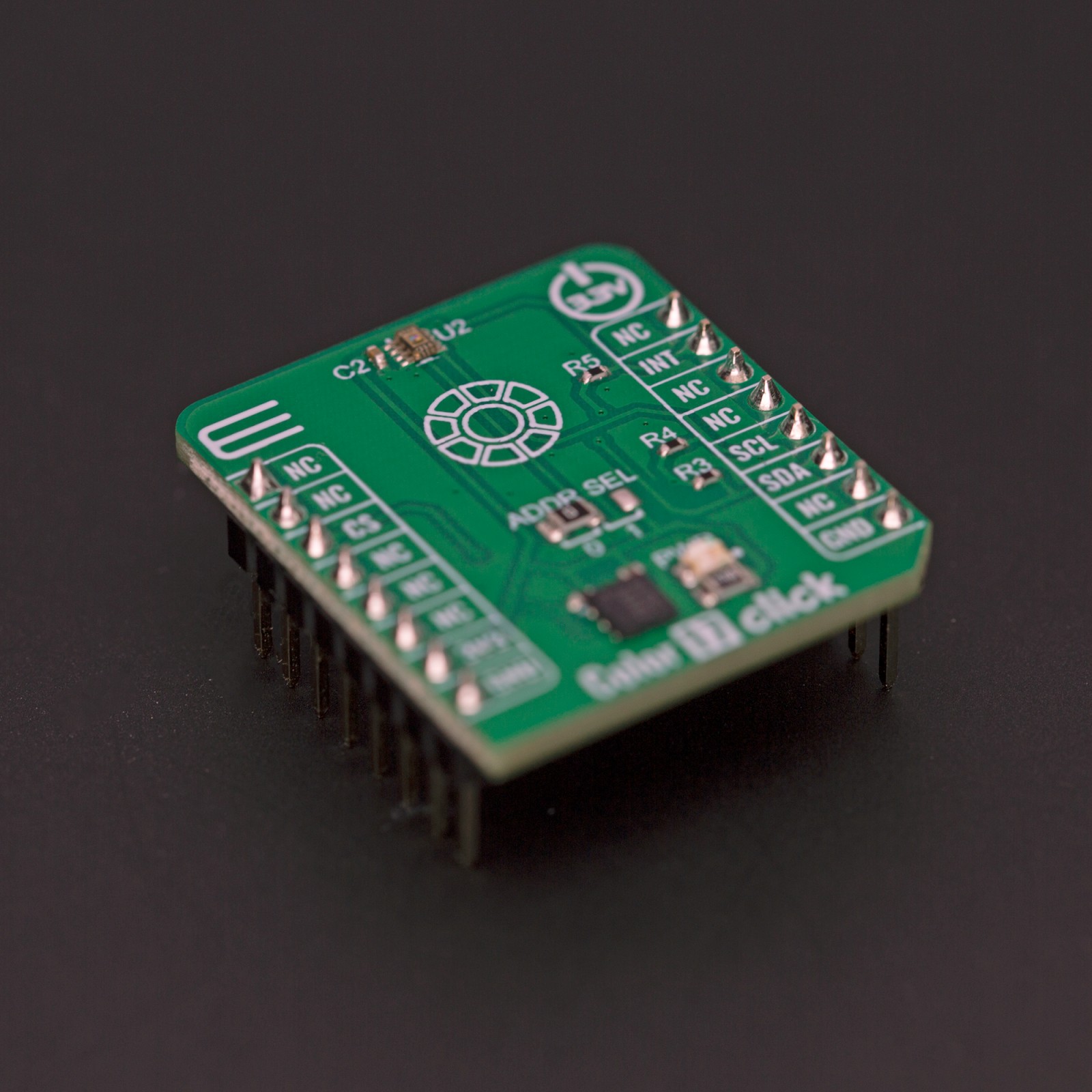
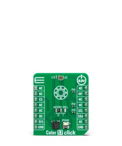
The Color 17 Click uses an I2C 2-Wire interface supporting a Fast mode of up to 400KHz, and I2C burst mode to communicate with the host MCU. The I2C address can be selected via the ADDR SEL jumper with 0 selected by default. The sensor has several modes of operation: Power-Down mode, Continuous mode as a normal mode of operation, and a one-shot mode in which the sensor can be triggered to work depending on the user setup. One of the triggers can be the interrupt functionality, where the INT pin is used for hardware-synchronized triggers and interrupts. The OPT4084 features a threshold detection logic that allows MCU to sleep or do other things while the sensor watches when an appropriate interrupt event occurs.
This Click board™ can only be operated with a 3.3V logic voltage level. The board must perform appropriate logic voltage level conversion before using MCUs with different logic levels. However, the Click board™ comes equipped with a library containing functions and an example code that can be used, as a reference, for further development.
Specifications
Type
Optical
Applications
Can be used for the development of applications for camera image correction, auto white balancing, lighting control systems, building automation and control, or general display brightness and color adjustments
On-board modules
OPT4048 – high-speed precision tristimulus XYZ color sensor from Texas Instruments
Key Features
Four channels for close mimic of the human eye spectra, high precision and resolution, built-in automatic full-scale light range selection, configurable conversion times, reject the NIR region, interrupt and hardware synchronized triggers, low power consumption, and more
Interface
I2C
Feature
ClickID
Compatibility
mikroBUS™
Click board size
S (28.6 x 25.4 mm)
Input Voltage
3.3V
Pinout diagram
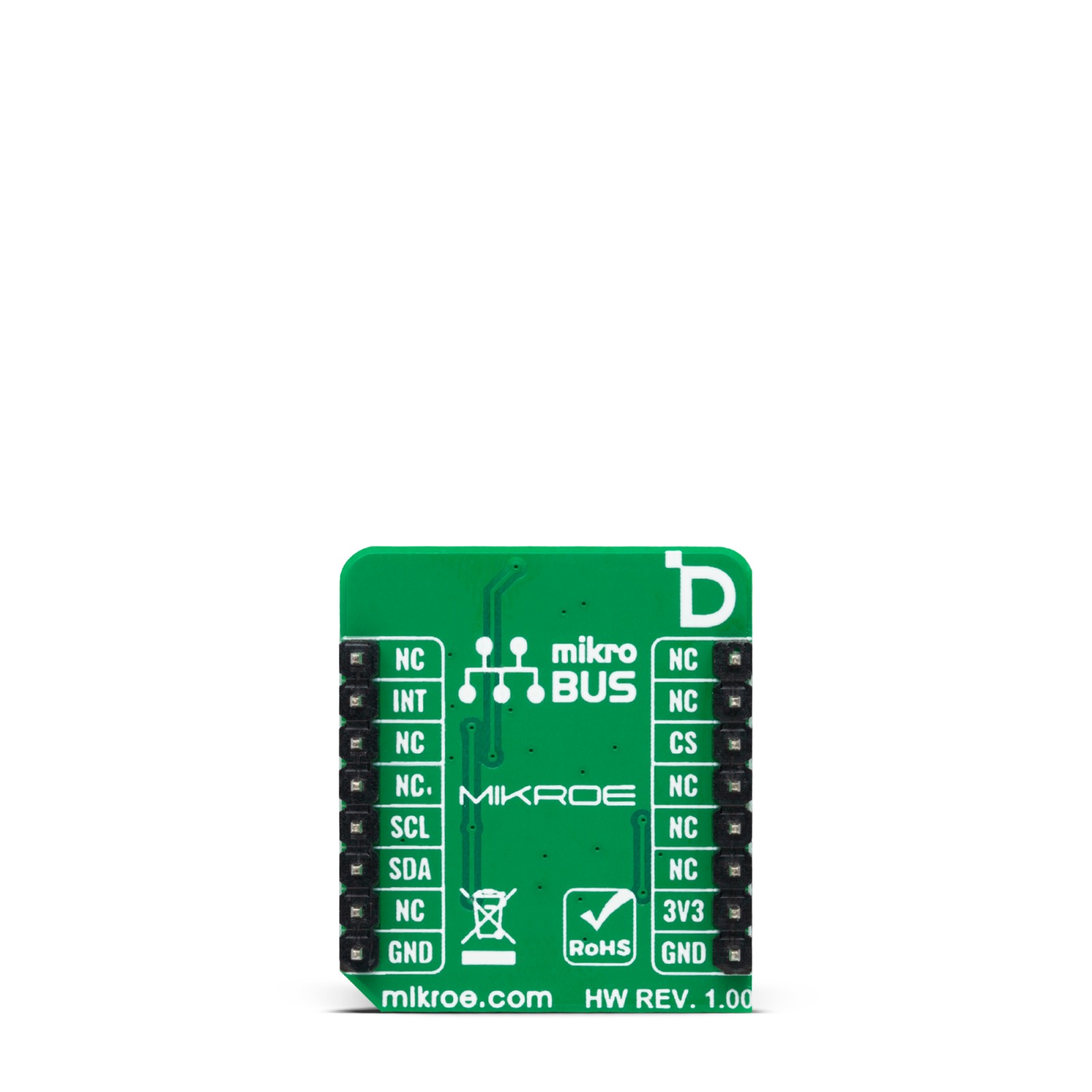
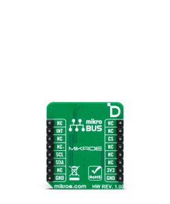
This table shows how the pinout on Color 17 Click corresponds to the pinout on the mikroBUS™ socket (the latter shown in the two middle columns).
Onboard settings and indicators
Label | Name | Default | Description |
---|---|---|---|
LD1 | PWR | – | Power LED Indicator |
JP1 | ADDR SEL | Left | I2C Address Selection 0/1: Left position 0, Right position 1 |
Color 17 Click electrical specifications
Description | Min | Typ | Max | Unit |
---|---|---|---|---|
Supply Voltage | – | 3.3 | – | V |
Lux Detection Range | – | – | 144 | klux |
Peak Wavelength (X/Y/Z/W) | 600/550/460/500 | nm | ||
Resolution | 9 | – | 20 | bits |
Software Support
We provide a library for the Color 17 Click as well as a demo application (example), developed using MIKROE compilers. The demo can run on all the main MIKROE development boards.
Package can be downloaded/installed directly from NECTO Studio Package Manager (recommended), downloaded from our LibStock™ or found on Mikroe github account.
Library Description
This library contains API for Color 17 Click driver.
Key functions
-
color17_get_cct
Color 17 gets correlated color temperature data function. -
color17_get_measurement
Color 17 gets light and color measurement data function. -
color17_set_config
Color 17 set the configuration function.
Example Description
This library contains API for the Color 17 Click driver. This example displays CCT data, Light intensity level and the light color names.
void application_task ( void )
{
if ( COLOR17_OK == color17_get_cct( &color17, &cct, &light_intensity ) )
{
log_printf( &logger, " CCT: %.2frn", cct );
log_printf( &logger, " LIL: %.2frn", light_intensity );
}
log_printf( &logger, " - - - - - - - - - - - rn" );
display_color( );
log_printf( &logger, " ----------------------rn" );
Delay_ms( 1000 );
}
The full application code, and ready to use projects can be installed directly from NECTO Studio Package Manager (recommended), downloaded from our LibStock™ or found on Mikroe github account.
Other Mikroe Libraries used in the example:
- MikroSDK.Board
- MikroSDK.Log
- Click.Color17
Additional notes and informations
Depending on the development board you are using, you may need USB UART click, USB UART 2 Click or RS232 Click to connect to your PC, for development systems with no UART to USB interface available on the board. UART terminal is available in all MIKROE compilers.
mikroSDK
This Click board™ is supported with mikroSDK – MIKROE Software Development Kit, that needs to be downloaded from the LibStock and installed for the compiler you are using to ensure proper operation of mikroSDK compliant Click board™ demo applications.
For more information about mikroSDK, visit the official page.