How does it work?
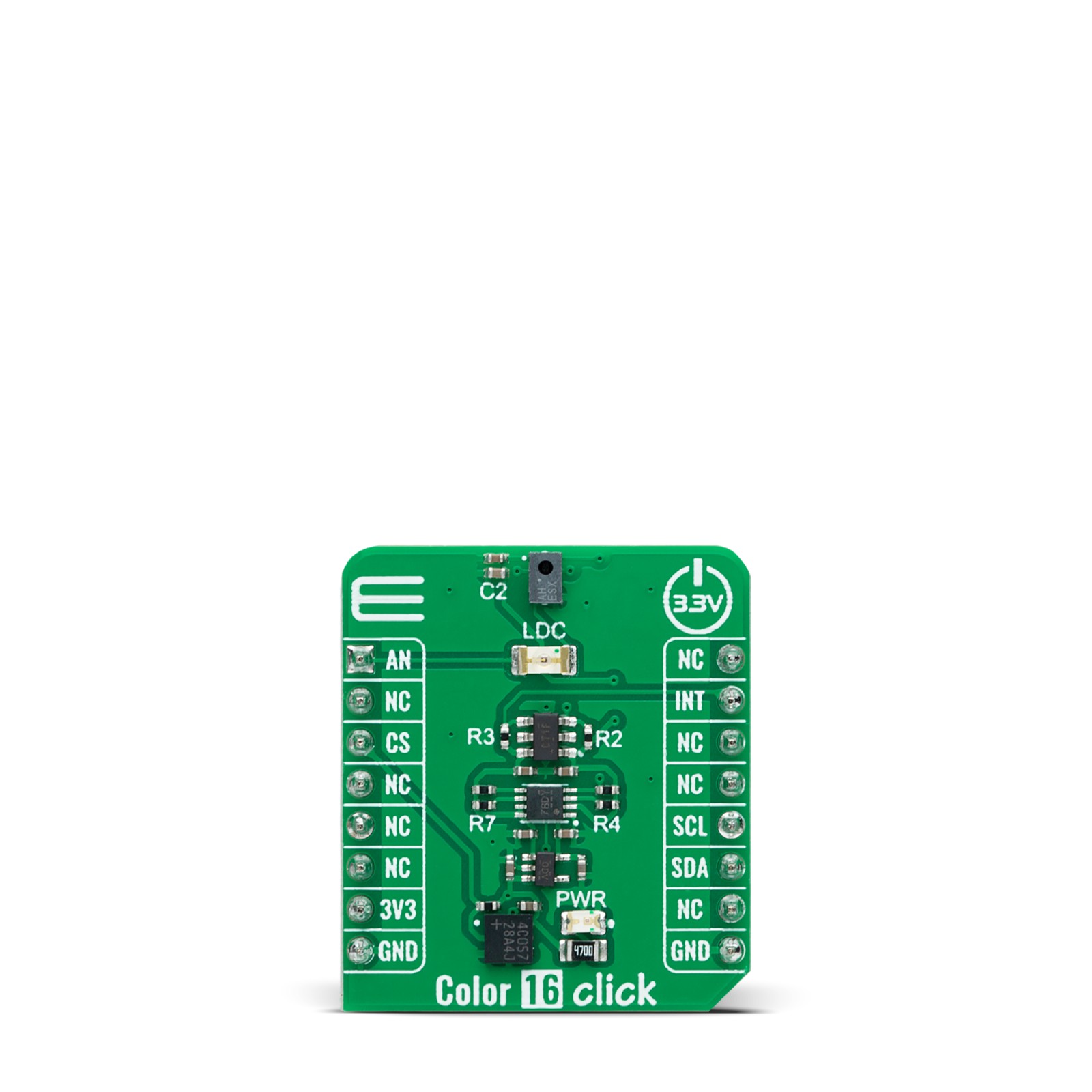
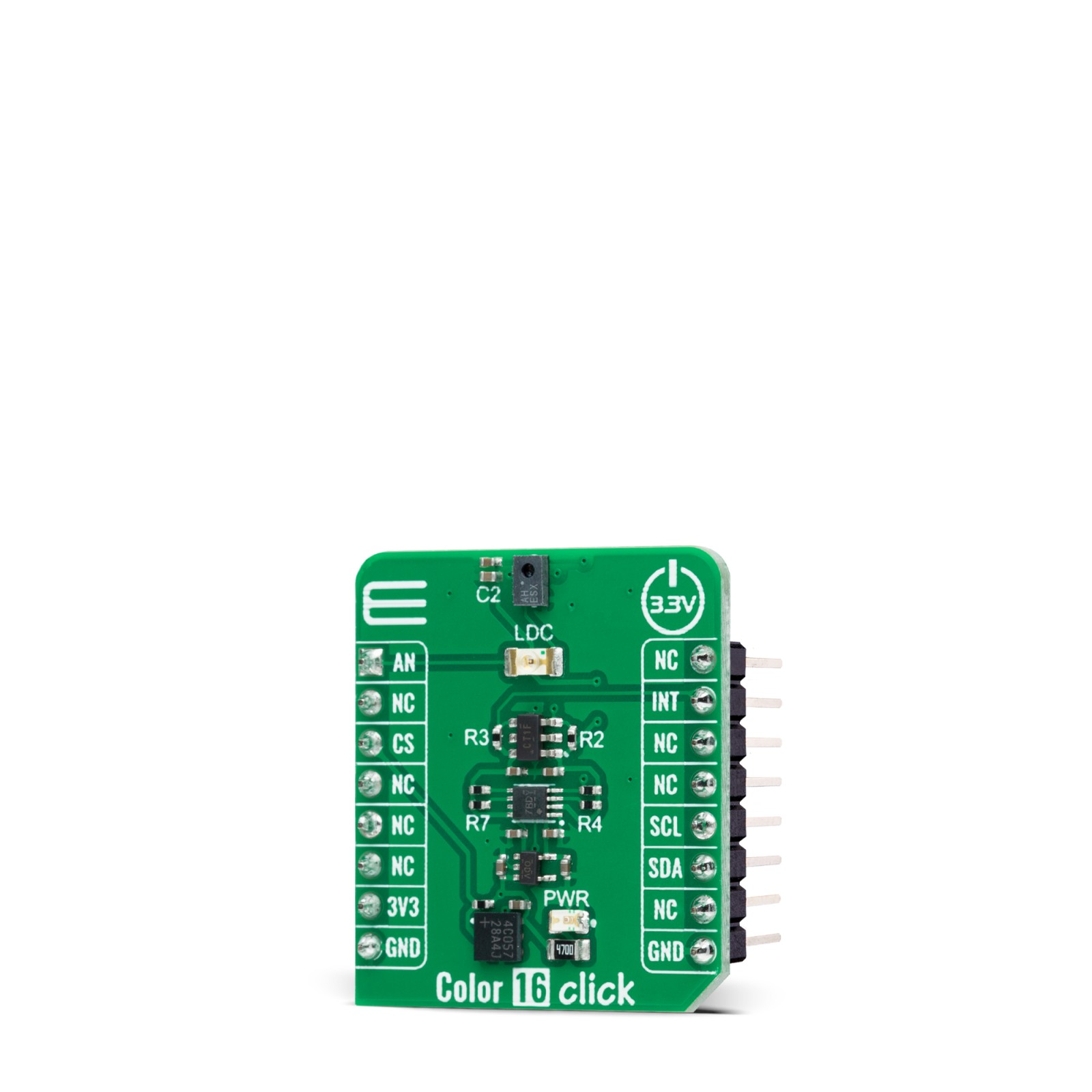
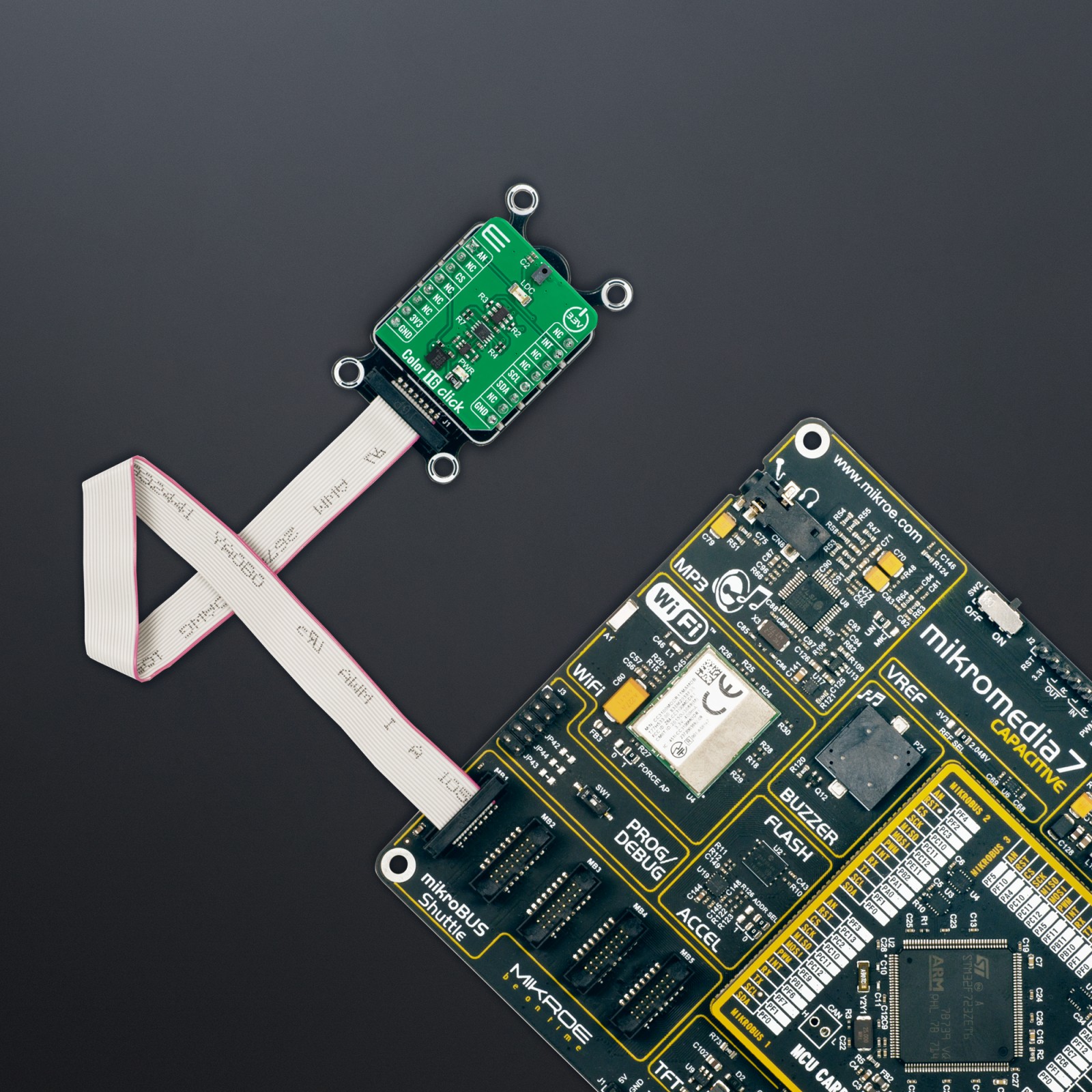
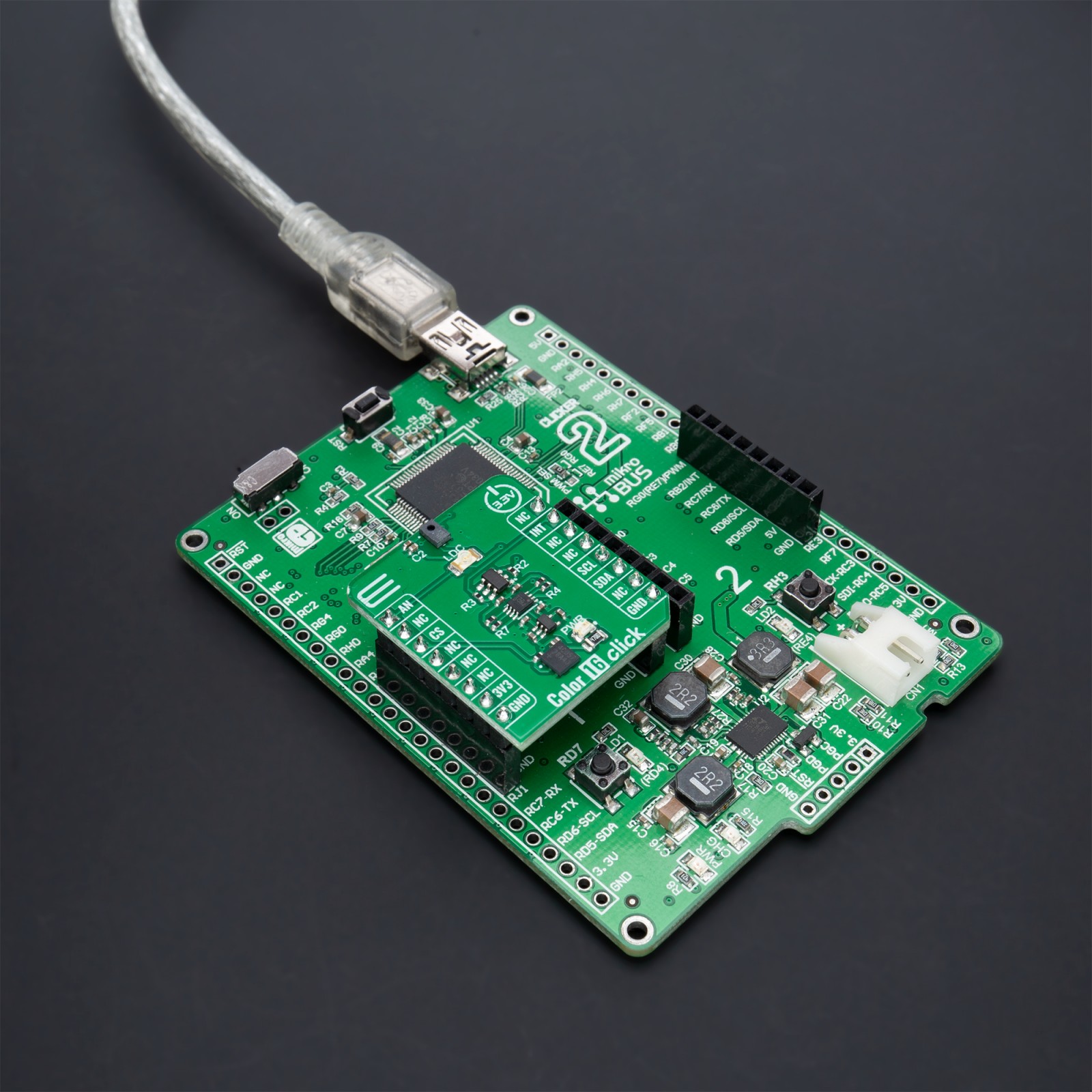
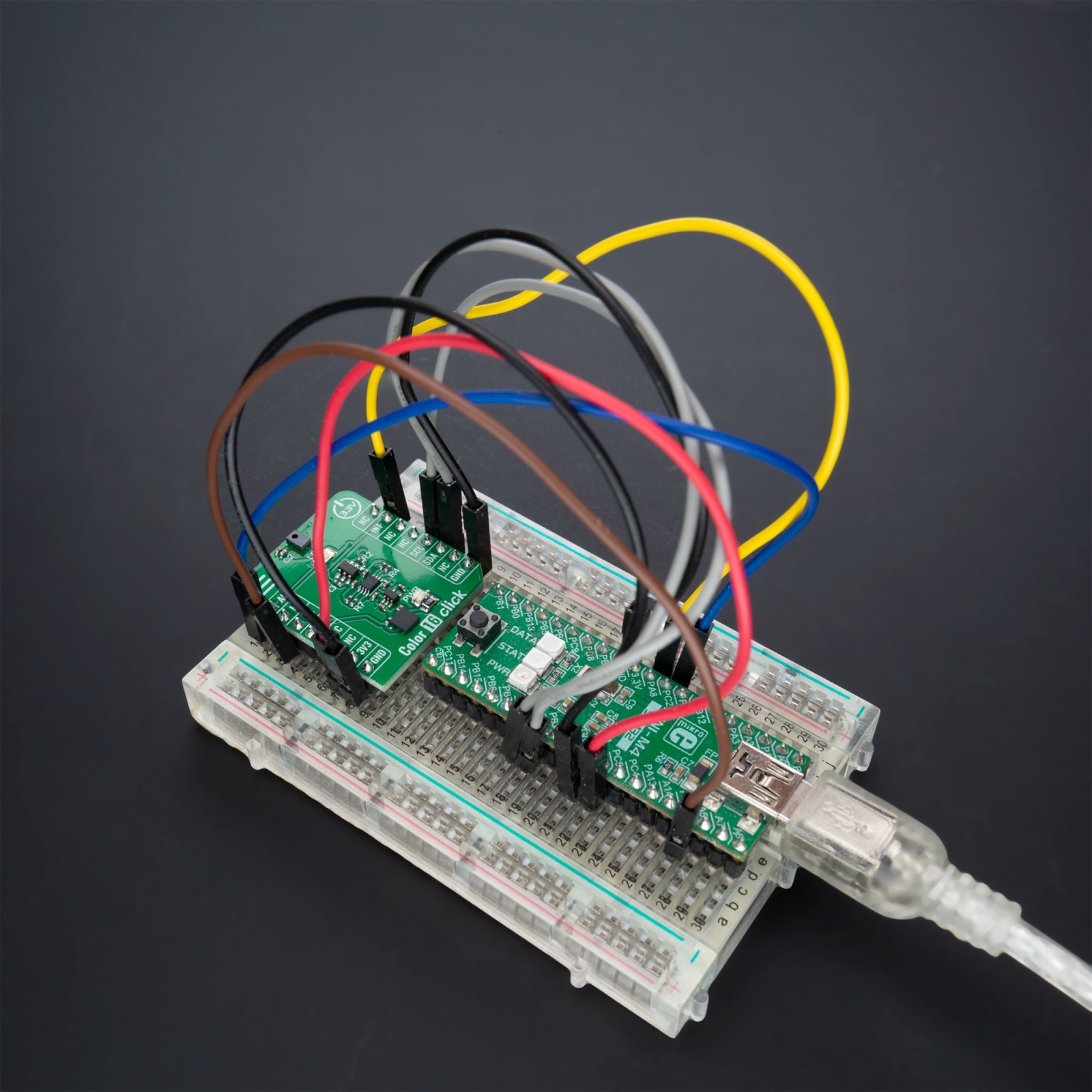
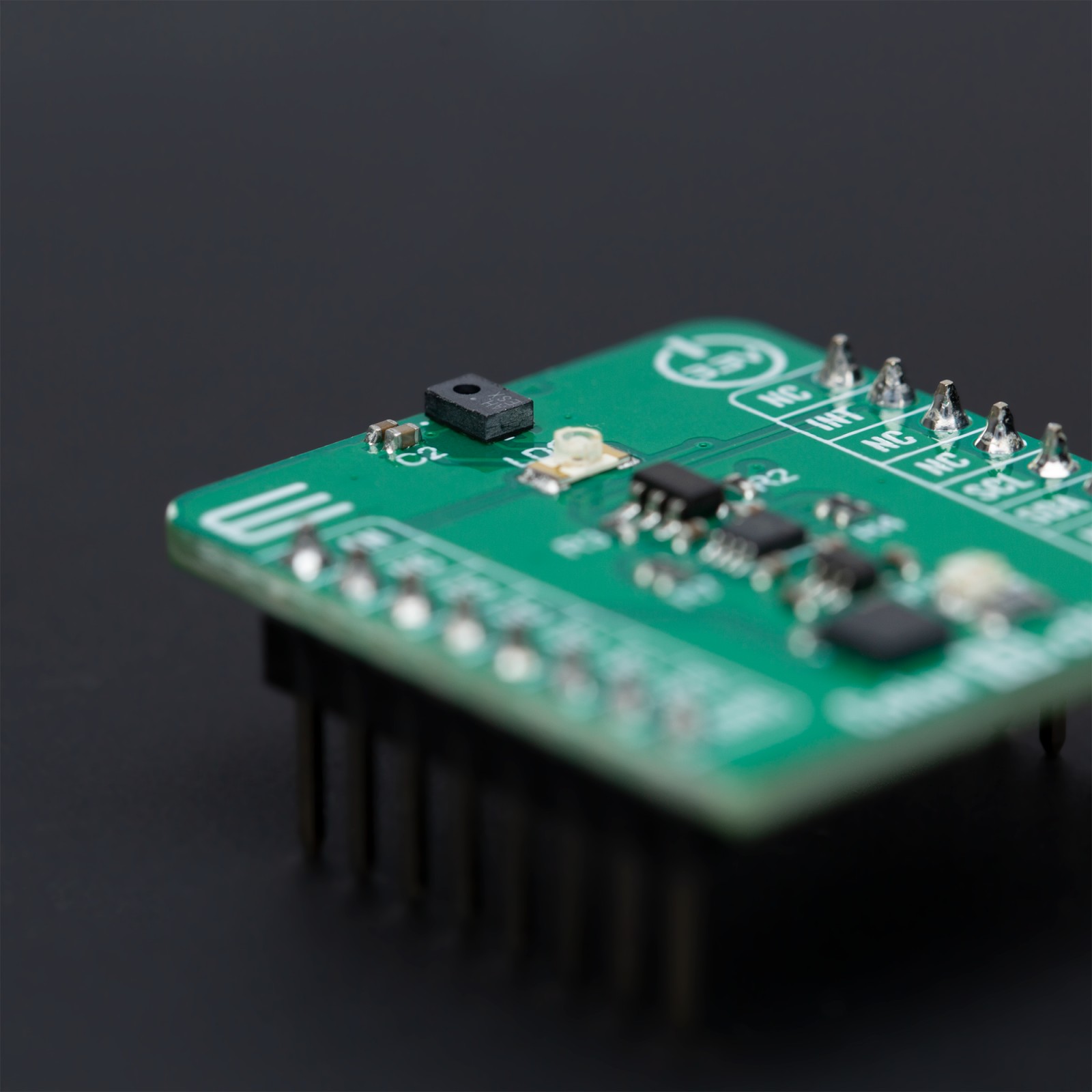
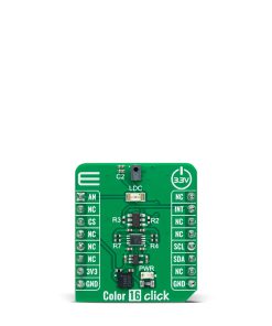
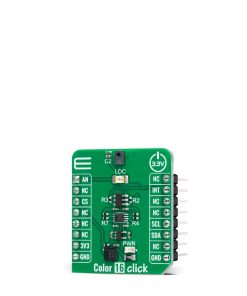
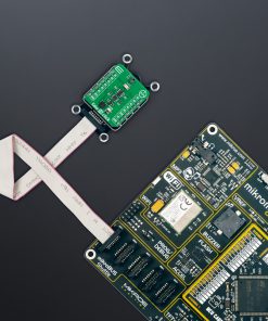
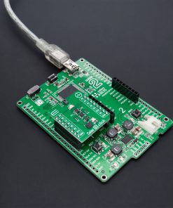
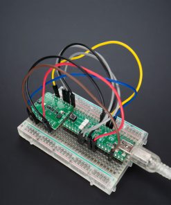
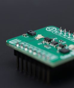
Color 16 Click is based on the AS7343, a 14-channel multi-purpose spectral sensor from ams AG, providing fast and accurate spectral measurements. It is optimized for reflective (thanks to an onboard LDC red LED controlled through AN pin of the mikroBUS™ socket), transmissive, and emissive light applications, including color matching, fluid or reagent analysis, lateral flow test applications, and spectral identification in the visible range. The AS7343 has a built-in aperture that controls the light entering the sensor array to increase accuracy. The spectral response is defined by individual channels covering approximately 380nm to 1000nm with 11 channels centered in the visible spectrum, one near-infrared, and a clear channel.
The AS7343 features a 5×5 photodiode array. Above and below the array there are two photodiodes with dedicated functions such as flicker detection and near-infrared response, while in each corner, the array has a photodiode without filter that is responsive in the visible spectral range. The AS7343 can detect 14 channels – 12 wavelengths, plus a clear and flicker output channel – making this Click board™ great for LED color calibration, miniature optical spectrometers, and more.
This sensor does not need a specific Power-Up sequence but requires a voltage of 1.8V for its interface and logic part to work correctly. Therefore, a small regulating LDO, the TLV700, provides a 1.8V out of 3.3V mikroBUS™ power rail.
Color 16 Click communicates with MCU using the standard I2C 2-Wire interface with a maximum clock frequency of 400kHz, fully adjustable through software registers. Since the sensor for operation requires a power supply of 1.8V, this Click board™ also features the PCA9306 and SN74LVC1T45 voltage-level translators. The I2C interface bus lines are routed to the voltage-level translators allowing this Click board™ to work with 3.3V MCU properly. Also, it uses an interrupt pin, the INT pin of the mikroBUS™ socket, used when an interrupt occurs to alert the system when the color result crosses upper or lower threshold settings.
This Click board™ can be operated only with a 3.3V logic voltage level. The board must perform appropriate logic voltage level conversion before using MCUs with different logic levels. However, the Click board™ comes equipped with a library containing functions and an example code that can be used as a reference for further development.
Specifications
Type
Color Sensing,Optical
Applications
Can be used for reflective, transmissive, and emissive light applications
On-board modules
AS7343 – multi-purpose spectral sensor from ams AG
Key Features
14 optical channels distributed over visible spectrum, near-infrared, and clear channel, dedicated functions such as flicker detection, high senistivity, fast measurements, low power consumption, interrupt, and more
Interface
I2C
Feature
ClickID
Compatibility
mikroBUS™
Click board size
S (28.6 x 25.4 mm)
Input Voltage
3.3V
Pinout diagram
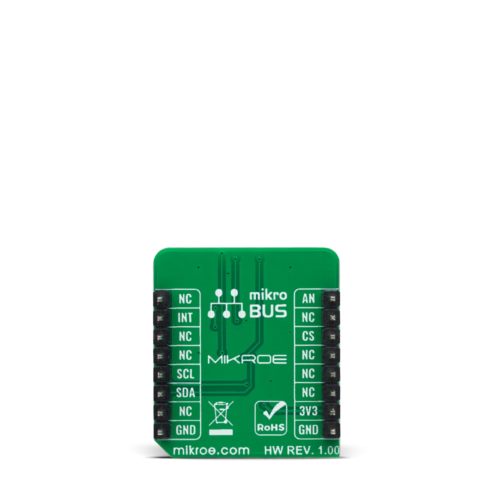
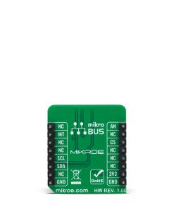
This table shows how the pinout on Color 16 Click corresponds to the pinout on the mikroBUS™ socket (the latter shown in the two middle columns).
Onboard settings and indicators
Label | Name | Default | Description |
---|---|---|---|
LD1 | PWR | – | Power LED Indicator |
LD2 | LDC | – | Light Source |
Color 16 Click electrical specifications
Description | Min | Typ | Max | Unit |
---|---|---|---|---|
Supply Voltage | – | 3.3 | – | V |
Spectral Range | 380 | – | 1000 | nm |
Software Support
We provide a library for the Color 16 Click as well as a demo application (example), developed using Mikroe compilers. The demo can run on all the main Mikroe development boards.
Package can be downloaded/installed directly from NECTO Studio Package Manager(recommended), downloaded from our LibStock™ or found on Mikroe github account.
Library Description
This library contains API for Color 16 Click driver.
Key functions
-
color16_read_data
This function checks if the spectral measurement data is ready and then reads data from all channels along with the STATUS and ASTATUS bytes. -
color16_set_wait_time_ms
This function sets the wait time in milliseconds by setting the WTIME register. -
color16_set_integration_time_ms
This function sets the integration time in milliseconds by setting the ATIME and ASTEP registers.
Example Description
This example demonstrates the use of Color 16 Click boards™ by reading and displaying the values from all 14 channels.
void application_task ( void )
{
color16_data_t color_data;
if ( COLOR16_OK == color16_read_data ( &color16, &color_data ) )
{
log_printf ( &logger, " STATUS: 0x%.2Xrn", ( uint16_t ) color_data.status );
log_printf ( &logger, " ASTATUS: 0x%.2Xrn", ( uint16_t ) color_data.astatus );
log_printf ( &logger, " ------- Cycle 1 -------rn" );
log_printf ( &logger, " Channel FZ: %urn", color_data.ch_fz );
log_printf ( &logger, " Channel FY: %urn", color_data.ch_fy );
log_printf ( &logger, " Channel FXL: %urn", color_data.ch_fxl );
log_printf ( &logger, " Channel NIR: %urn", color_data.ch_nir );
log_printf ( &logger, " Channel 2xVIS_1: %urn", color_data.ch_2x_vis_1 );
log_printf ( &logger, " Channel FD_1: %urn", color_data.ch_fd_1 );
log_printf ( &logger, " ------- Cycle 2 -------rn" );
log_printf ( &logger, " Channel F2: %urn", color_data.ch_f2 );
log_printf ( &logger, " Channel F3: %urn", color_data.ch_f3 );
log_printf ( &logger, " Channel F4: %urn", color_data.ch_f4 );
log_printf ( &logger, " Channel F6: %urn", color_data.ch_f6 );
log_printf ( &logger, " Channel 2xVIS_2: %urn", color_data.ch_2x_vis_2 );
log_printf ( &logger, " Channel FD_2: %urn", color_data.ch_fd_2 );
log_printf ( &logger, " ------- Cycle 3 -------rn" );
log_printf ( &logger, " Channel F1: %urn", color_data.ch_f1 );
log_printf ( &logger, " Channel F5: %urn", color_data.ch_f5 );
log_printf ( &logger, " Channel F7: %urn", color_data.ch_f7 );
log_printf ( &logger, " Channel F8: %urn", color_data.ch_f8 );
log_printf ( &logger, " Channel 2xVIS_3: %urn", color_data.ch_2x_vis_3 );
log_printf ( &logger, " Channel FD_3: %urn", color_data.ch_fd_3 );
log_printf ( &logger, " -----------------------rnn" );
Delay_ms ( 300 );
}
}
The full application code, and ready to use projects can be installed directly from NECTO Studio Package Manager(recommended), downloaded from our LibStock™ or found on Mikroe github account.
Other Mikroe Libraries used in the example:
- MikroSDK.Board
- MikroSDK.Log
- Click.Color16
Additional notes and informations
Depending on the development board you are using, you may need USB UART click, USB UART 2 Click or RS232 Click to connect to your PC, for development systems with no UART to USB interface available on the board. UART terminal is available in all Mikroe compilers.
mikroSDK
This Click board™ is supported with mikroSDK – Mikroe Software Development Kit. To ensure proper operation of mikroSDK compliant Click board™ demo applications, mikroSDK should be downloaded from the LibStock and installed for the compiler you are using.
For more information about mikroSDK, visit the official page.