How does it work?
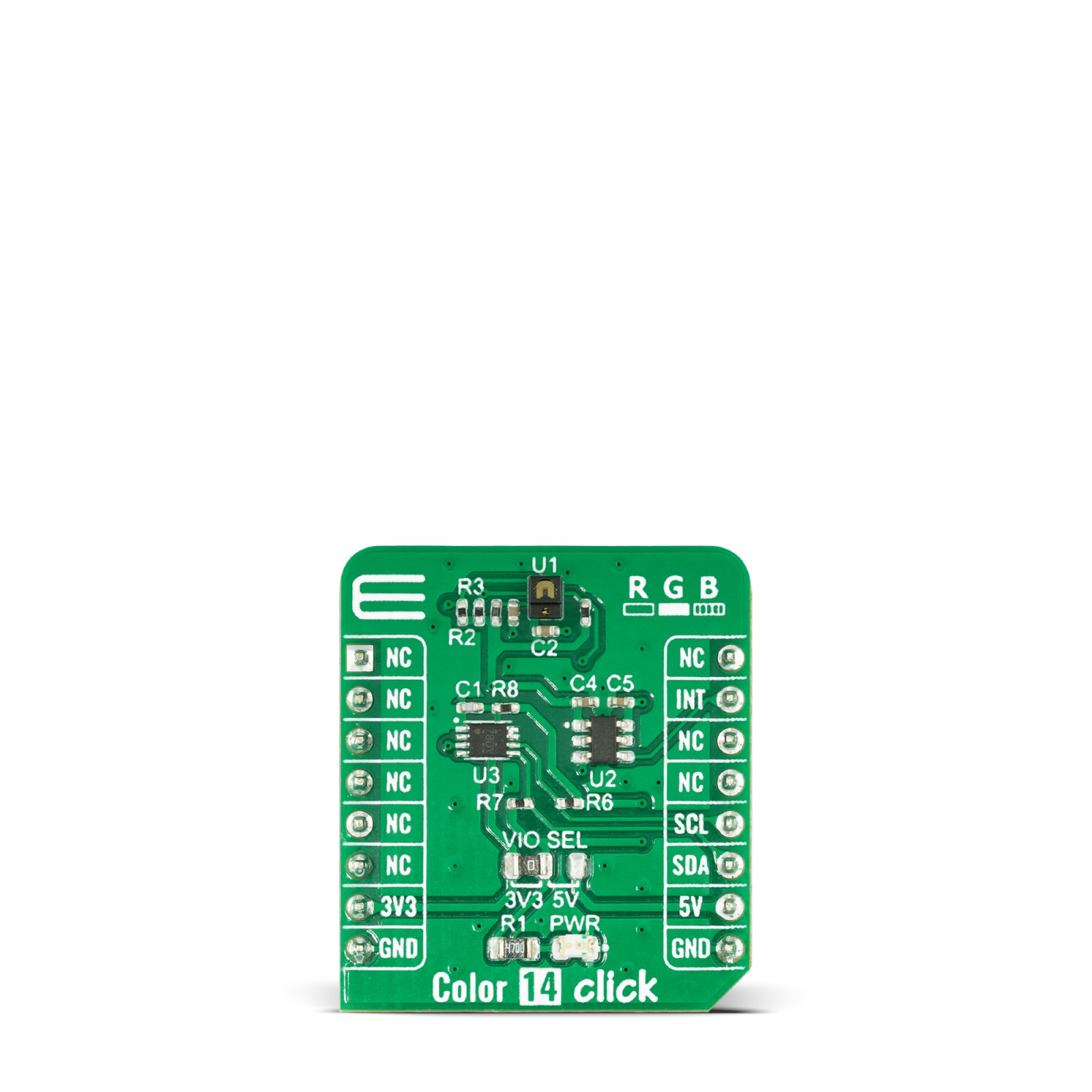
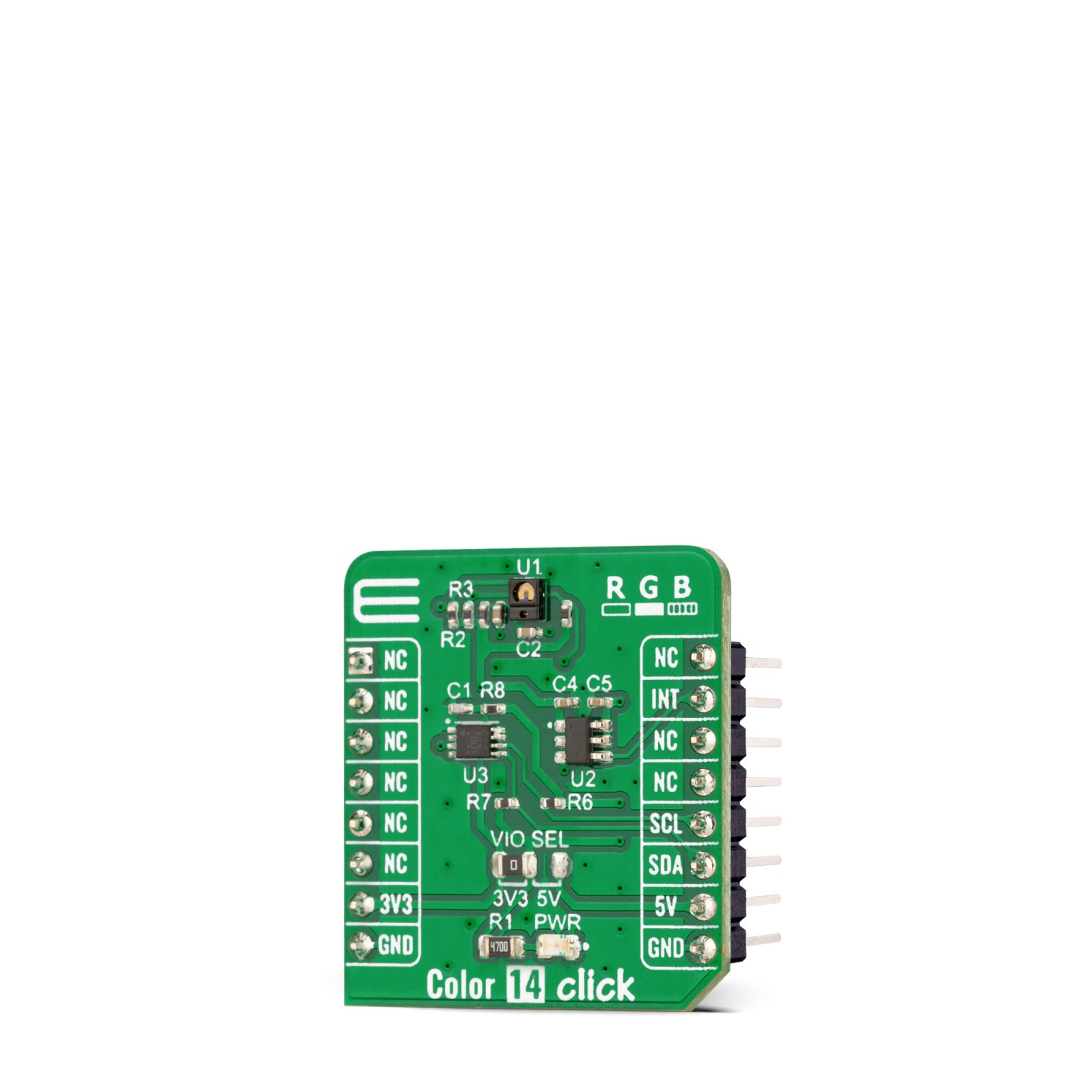
Color 14 Click as its foundation uses the APDS-9151, a digital I2C compatible interface ambient light sensor (ALS), RGB, and proximity sensor with IR LED from Broadcom Limited. It uses four channels (Red, Green, Blue, and IR) in a specially designed matrix arrangement to achieve optimal angular response and accurate RGB spectral response with high lux accuracy over various light sources. It is suitable for use under a small aperture of the devices’ cover windows, providing optimum viewing in diverse lighting conditions.
The proximity detection feature operates well from bright sunlight to dark rooms. Proximity resolution can vary from 8bits to 11bits, with the measurement rate from 6.25ms to 400ms. To offset unwanted reflected light from the cover glass, a proximity detection (PS) intelligent cancellation level register allows for an on-chip subtraction of the ADC count caused by the unwanted reflected light from PS ADC output. Both the PS and ALS function independently provides maximum flexibility in application.
The APDS-9151 has a wide dynamic range, with a programmable current in eight different steps and the LED modulation frequency, which can be set from 60kHz to 100kHz in five steps. The addition of the micro-optics lenses within the module provides highly efficient transmission and reception of infrared energy, which lowers overall power dissipation. In addition, the device can be put into a low-power Standby mode providing low average power consumption.
Color 14 Click communicates with MCU using the standard I2C 2-Wire interface with a frequency of 100kHz in Standard and up to 400kHz in Fast Mode. Since the sensor is supplied with a 3.3V logic voltage level only, the Color 14 Click also features a PCA9306 and SN74LVC1T45 voltage-level translators, allowing this Click board™ to be interfaced with both 3.3V and 5V MCUs. It also generates flexible ambient and proximity programmable interrupt signals routed on the INT pin of the mikroBUS™ socket, which is triggered if upper or lower threshold values are crossed. It is also possible to deactivate both sensors after a specific interrupt event occurs.
This Click board™ can operate with both 3.3V and 5V logic voltage levels selected via the VIO SEL jumper. This way, it is allowed for both 3.3V and 5V capable MCUs to use the I2C communication lines properly. However, the Click board™ comes equipped with a library containing easy-to-use functions and an example code that can be used, as a reference, for further development.
Specifications
Type
Color Sensing,Optical
Applications
Can be used for accurately measuring the subtlest changes in light, ambient light, and proximity detection allowing for maximum flexibility in applications
On-board modules
APDS-9151 – digital I2C compatible interface ambient light sensor (ALS), RGB, and proximity sensor with IR LED from Broadcom Limited
Key Features
Low power consumption, high precission, individual channels for red, green, blue, and infrared, approximates human eye response with green channel, light output proportional to light intensity, works well under different light source conditions, low light sensitivity, programmable interrupt, and more
Interface
I2C
Feature
No ClickID
Compatibility
mikroBUS™
Click board size
S (28.6 x 25.4 mm)
Input Voltage
3.3V or 5V
Pinout diagram
This table shows how the pinout on Color 14 Click corresponds to the pinout on the mikroBUS™ socket (the latter shown in the two middle columns).
Onboard settings and indicators
Label | Name | Default | Description |
---|---|---|---|
LD1 | PWR | – | Power LED Indicator |
JP1 | VIO SEL | Left | Logic Level Voltage Selection 3V3/5V: Left position 3V3, Right position 5V |
Color 14 Click electrical specifications
Description | Min | Typ | Max | Unit |
---|---|---|---|---|
Supply Voltage | 3.3 | – | 5 | V |
Detection Range | 0 | – | 60 | mm |
Peak Wavelength (R/G/B) | 610/550/470 | nm | ||
Peak Wavelength (IR) | – | 950 | – | nm |
Operating Temperature Range | -40 | +25 | +85 | °C |
Software Support
We provide a library for the Color 14 Click as well as a demo application (example), developed using MikroElektronika compilers. The demo can run on all the main MikroElektronika development boards.
Package can be downloaded/installed directly from NECTO Studio Package Manager(recommended way), downloaded from our LibStock™ or found on Mikroe github account.
Library Description
This library contains API for Color 14 Click driver.
Key functions:
color14_cfg_setup
– Config Object Initialization function.color14_init
– Initialization function.
Example description
This application showcases ability of click board to read RGB and IR data from device. Also it can be configured to read proximity data and ALS data in lux units.
void application_task ( void ) { switch ( example_type ) { case COLOR14_EXAMPLE_PS_LS: { color14_proximity_als_example( ); break; } case COLOR14_EXAMPLE_RGB: { color14_rgb_example( ); break; } default: { log_error( &logger, " Select example!" ); break; } } Delay_ms( 500 ); }
The full application code, and ready to use projects can be installed directly from NECTO Studio Package Manager(recommended way), downloaded from our LibStock™ or found on Mikroe github account.
Other Mikroe Libraries used in the example:
- MikroSDK.Board
- MikroSDK.Log
- Click.Color14
Additional notes and informations
Depending on the development board you are using, you may need USB UART click, USB UART 2 click or RS232 click to connect to your PC, for development systems with no UART to USB interface available on the board. The terminal available in all MikroElektronika compilers, or any other terminal application of your choice, can be used to read the message.
mikroSDK
This Click board™ is supported with mikroSDK – MikroElektronika Software Development Kit. To ensure proper operation of mikroSDK compliant Click board™ demo applications, mikroSDK should be downloaded from the LibStock and installed for the compiler you are using.
For more information about mikroSDK, visit the official page.