-
×
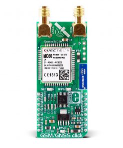
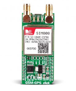 GSM-GPS Click
1 × R1,300.00
GSM-GPS Click
1 × R1,300.00
Subtotal: R1,300.00


R1,200.00 ex. VAT
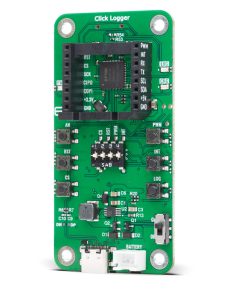
Click Logger is a specialized development tool designed for data logging and real-time monitoring of mikroBUS™-compatible Click boards™. It functions as both a UART Logger, capturing and storing data from the mikroBUS™ TX line onto a microSD card via an ATmega328P microcontroller, and a mikroBUS™ to USB adapter for serial communication using the FT4232H chip.
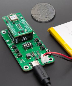
With additional features like a power monitoring for real-time voltage, current, and power measurements, a built-in Li-Po battery charger for portable use, and versatile GPIO control, Click Logger is an essential tool for developers working on Click board-based projects, ensuring reliable data acquisition and streamlined debugging in both lab and field environments.
Stock: Lead-time applicable.
| 5+ | R1,140.00 |
| 10+ | R1,080.00 |
| 15+ | R1,020.00 |
| 20+ | R981.60 |
Click Logger is a versatile tool for Click board™ development, combining USB connectivity and UART data logging into a single compact board. It serves two primary functions:
.jpg)
With its combination of real-time monitoring, data logging, and flexible connectivity, Click Logger is an essential tool for engineers and developers working with mikroBUS™-based hardware.
Type
Shield
Applications
Ideal for real-time data monitoring, efficient logging, and testing of mikroBUS™-compatible hardware in both lab and field application
On-board modules
FT4232H – USB to UART converter from FTDI | ATmega328P – 8-bit AVR MCU from Microchip
Key Features
mikroBUS™ to USB Adapter, UART logger functionality, ATmega328P for UART logging and data storage, USB MIKROE VID and LOGGER PID parameters, battery support, LED indicators, GPIO control, ICSP connector for MCU reprogramming, power monitor, compact and portable, and more
Interface
Analog,GPIO,I2C,PWM,SPI,UART,USB
Feature
No ClickID
mikroBUS No.
1
Supply Voltage
Battery, USB
Category
Bundles-Kits-Sheilds
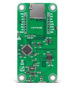
This table shows how the pinout on Click Logger corresponds to the pinout on the mikroBUS™ socket (the latter shown in the two middle columns).
| Notes | Pin | Pin | Notes | ||||
|---|---|---|---|---|---|---|---|
| Analog Output | AN | 1 | AN | PWM | 16 | PWM | PWM Signal |
| Reset / ID SEL | RST | 2 | RST | INT | 15 | INT | Interrupt |
| SPI Select / ID COMM | CS | 3 | CS | RX | 14 | TX | UART TX |
| SPI Clock | SCK | 4 | SCK | TX | 13 | RX | UART RX |
| SPI Data OUT | SDO | 5 | MISO | SCL | 12 | SCL | I2C Clock |
| SPI Data IN | SDI | 6 | MOSI | SDA | 11 | SDA | I2C Data |
| Power Supply | 3.3V | 7 | 3.3V | 5V | 10 | 5V | Power Supply |
| Ground | GND | 8 | GND | GND | 9 | GND | Ground |
| Label | Name | Default | Description |
|---|---|---|---|
| LD1 | CHG | – | Battery Charging LED Indicator |
| LD2 | PWR | – | Power LED Indicator |
| LD2 | LOG | – | MicroSD Card Log LED Indicator |
| T1-T5 | AN/CS/RST/PWM/INT | – | mikroBUS™ Module Control Buttons |
| T6 | LOG | – | Logging Process Control Button |
| SW1 | – | – | mikroBUS™ Module Control Switches |
| Description | Min | Typ | Max | Unit |
|---|---|---|---|---|
| USB Supply Voltage | – | 5 | – | V |
| Battery Supply Voltage | 3.4 | 4.1 | 4.2 | V |
MIKROE does not currently provide software support for Click Logger board in the form of libraries, functions, or example code. For additional information or assistance, we recommend reaching out to u-blox. Find more details at the following resources:
| Weight | 35 g |
|---|---|
| Brand | MikroElektronika |