Charger 28 Click
R530.00 ex. VAT
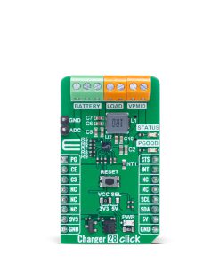
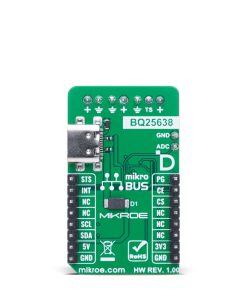
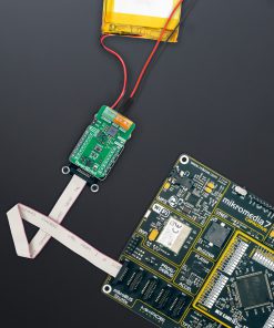
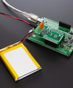
Charger 28 Click is a compact add-on board designed for safe, fast, and efficient charging of single-cell Li-Ion and Li-Polymer batteries. This board features the BQ25638, a 5A switch-mode battery charger from Texas Instruments, featuring NVDC power path management and advanced input optimization. It supports USB Type-C input, includes a battery connector with thermistor support, offers a dedicated load output, and features I2C communication with additional status and monitoring signals. It also provides comprehensive safety protections such as thermal regulation, overvoltage, and overcurrent protection, while supporting OTG functionality for reverse boost operation. This Click board™ is ideal for powering and charging solutions in gaming peripherals, computer accessories, and other portable electronic applications where reliable battery management and system stability are critical.
Charger 28 Click is fully compatible with the mikroBUS™ socket and can be used on any host system supporting the mikroBUS™ standard. It comes with the mikroSDK open-source libraries, offering unparalleled flexibility for evaluation and customization. What sets this Click board™ apart is the groundbreaking ClickID feature, enabling your host system to seamlessly and automatically detect and identify this add-on board.
Stock: Lead-time applicable.
| 5+ | R503.50 |
| 10+ | R477.00 |
| 15+ | R450.50 |
| 20+ | R433.54 |
How does it work?
Charger 28 Click is based on the BQ25638, a 5A switch-mode battery charger from Texas Instruments, featuring NVDC (Narrow VDC) power path management designed to provide fast and reliable charging for single-cell Li-Ion and Li-Polymer batteries. This advanced charger architecture allows the system to maintain operation even when the battery is deeply discharged or temporarily removed, making it ideal for applications in gaming and computer accessories where stable power delivery is crucial. Power is supplied to the Charger 28 Click through a USB Type-C connector, providing the necessary input voltage for proper operation. The BQ25638’s integrated Input Current Optimizer (ICO) enables the system to detect and use the maximum available power from the input source without risking overload. Furthermore, it fully supports USB On-the-Go (OTG) specifications, delivering a constant current limit of up to 3.2A, ensuring compatibility with a wide range of modern portable devices.

The power path management system maintains the system voltage slightly above the battery voltage but prevents it from dropping below a programmable minimum system voltage. When the input voltage or current limits are reached, it automatically reduces the battery charge current to protect the source. If the system load continues to increase, the battery supplements the system power until the demand is met, effectively preventing input overload and ensuring continuous operation.
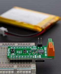
In addition to the charging input, Charger 28 Click provides a dedicated battery connector for attaching compatible batteries with voltages up to 4.8V. The middle pin of the battery connector is reserved for connecting an external thermistor if temperature monitoring is required. The BQ25638 operates autonomously to initiate and complete the charging cycle by monitoring the battery voltage and adapting the charging process across four distinct phases: trickle charge, pre-charge, constant current (CC) charge, and constant voltage (CV) charge. Upon completing the charging cycle, the charger terminates the process once the battery voltage exceeds the recharge threshold and the charge current falls below a preset level. Charging termination is supported across various temperature zones, including COOL, PRECOOL, NORMAL, WARM, and PREWARM, ensuring safe and optimized battery management under different conditions. If the battery voltage later drops below the programmed recharge threshold, the charging cycle restarts automatically to maintain optimal battery health.
For powering external loads, a LOAD connector is available next to the battery connector, enabling easy connection to the device or system that requires a power supply. Additionally, a VPMID connector is provided, carrying the positive rail of the charger’s output voltage, specifically designed for use in reverse boost mode applications such as power banks, where OTG functionality is required.
This Click board™ uses an I2C interface with clock speeds of up to 1MHz, ensuring fast communication with the host MCU. In addition to the I2C interface pins, Charger 28 Click features CE pin for charging enabling feature, an interrupt (INT) pin to report charger device status and fault to the host MCU, and a RESET button for resitting the charger. The board also features some visual indicators to provide real-time status updates. The STATUS LED reports the charging status and any fault conditions, while the PGOOD LED indicates if a good power source is present and above the programmable threshold. Both of these indicators are also available in digital format through STS and PG pins. The board also features pins routed to a 12-bit analog-to-digital converter (ADC) for monitoring charge current and input/battery/system voltages.
The charger provides various safety features for battery charging and system operations, including battery negative temperature coefficient (NTC) thermistor monitoring, charging safety timer and overvoltage and overcurrent protections. The thermal regulation reduces charge current when the junction temperature exceeds the programmable threshold.
This Click board™ can operate with either 3.3V or 5V logic voltage levels selected via the VCC SEL jumper. This way, both 3.3V and 5V capable MCUs can use the communication lines properly. Also, this Click board™ comes equipped with a library containing easy-to-use functions and an example code that can be used as a reference for further development.
Specifications
Type
Battery charger
Applications
Ideal for powering and charging solutions in gaming peripherals, computer accessories, and other portable electronic applications
On-board modules
BQ25638 – 5A switch-mode battery charger from Texas Instruments
Key Features
5A single-cell Li-Ion/Li-Polymer charger with NVDC power path, USB-C input, OTG support, ICO for input optimization, I2C interface, load and battery connectors, thermistor support, safety protections, dual logic voltage support, real-time status indicators, and more
Interface
I2C
Feature
ClickID
Compatibility
mikroBUS™
Click board size
M (42.9 x 25.4 mm)
Input Voltage
3.3V or 5V,External
Pinout diagram
This table shows how the pinout on Charger 28 Click corresponds to the pinout on the mikroBUS™ socket (the latter shown in the two middle columns).
| Notes | Pin | Pin | Notes | ||||
|---|---|---|---|---|---|---|---|
| Power-Good Indicator | PG | 1 | AN | PWM | 16 | STS | Charger Status Indicator |
| Charger Enable | CE | 2 | RST | INT | 15 | INT | Interrupt |
| ID COMM | CS | 3 | CS | RX | 14 | NC | |
| NC | 4 | SCK | TX | 13 | NC | ||
| NC | 5 | MISO | SCL | 12 | SCL | I2C Clock | |
| NC | 6 | MOSI | SDA | 11 | SDA | I2C Data | |
| Power Supply | 3.3V | 7 | 3.3V | 5V | 10 | 5V | Power Supply |
| Ground | GND | 8 | GND | GND | 9 | GND | Ground |
Onboard settings and indicators
| Label | Name | Default | Description |
|---|---|---|---|
| LD1 | PGOOD | – | Power Good LED Indicator |
| LD2 | STATUS | – | Status LED Indicator |
| LD3 | PWR | – | Power LED Indicator |
| JP1 | VCC SEL | Left | Power Voltage Level Selection 3V3/5V: Left position 3V3, Right position 5V |
| T1 | RESET | – | Reset Button |
Charger 28 Click electrical specifications
| Description | Min | Typ | Max | Unit |
|---|---|---|---|---|
| Supply Voltage | 3.3 | – | 5 | V |
| Charge Current | – | – | 5 | A |
Software Support
Charger 28 Click demo application is developed using the NECTO Studio, ensuring compatibility with mikroSDK‘s open-source libraries and tools. Designed for plug-and-play implementation and testing, the demo is fully compatible with all development, starter, and mikromedia boards featuring a mikroBUS™ socket.
Example Description
This example demonstrates the use of the Charger 28 Click board by monitoring various parameters of the charging system, such as input voltage (VBUS), battery voltage (VBAT), system voltage (VSYS), charging current (IBAT), and chip temperature (TDIE). Additionally, it reads and interprets the charger status and fault registers to provide detailed status and error feedback during operation.
Key Functions
charger28_cfg_setupConfig Object Initialization function.charger28_initInitialization function.charger28_default_cfgClick Default Configuration function.charger28_get_vbusThis function reads and calculates the bus voltage in millivolts.charger28_get_ibusThis function reads and calculates the input current in milliamperes.charger28_get_vbatThis function reads and calculates the battery voltage in millivolts.
Application Init
Initializes the driver and performs the default configuration of the Charger 28 Click by disabling charging, resetting registers, disabling the TS pin, configuring the ADC, and re-enabling charging.
Application Task
Periodically retrieves and logs charging parameters such as input voltage, battery voltage, system voltage, charging current, and temperature. The application also reads the status and fault registers to determine the current charging state and logs the information for debugging or monitoring purposes.
Application Output
This Click board can be interfaced and monitored in two ways:
- Application Output – Use the “Application Output” window in Debug mode for real-time data monitoring. Set it up properly by following this tutorial.
- UART Terminal – Monitor data via the UART Terminal using a USB to UART converter. For detailed instructions, check out this tutorial.
Additional Notes and Information
The complete application code and a ready-to-use project are available through the NECTO Studio Package Manager for direct installation in the NECTO Studio. The application code can also be found on the MIKROE GitHub account.
Resources
Downloads
| Weight | 20 g |
|---|---|
| Brand | MikroElektronika |