How does it work?
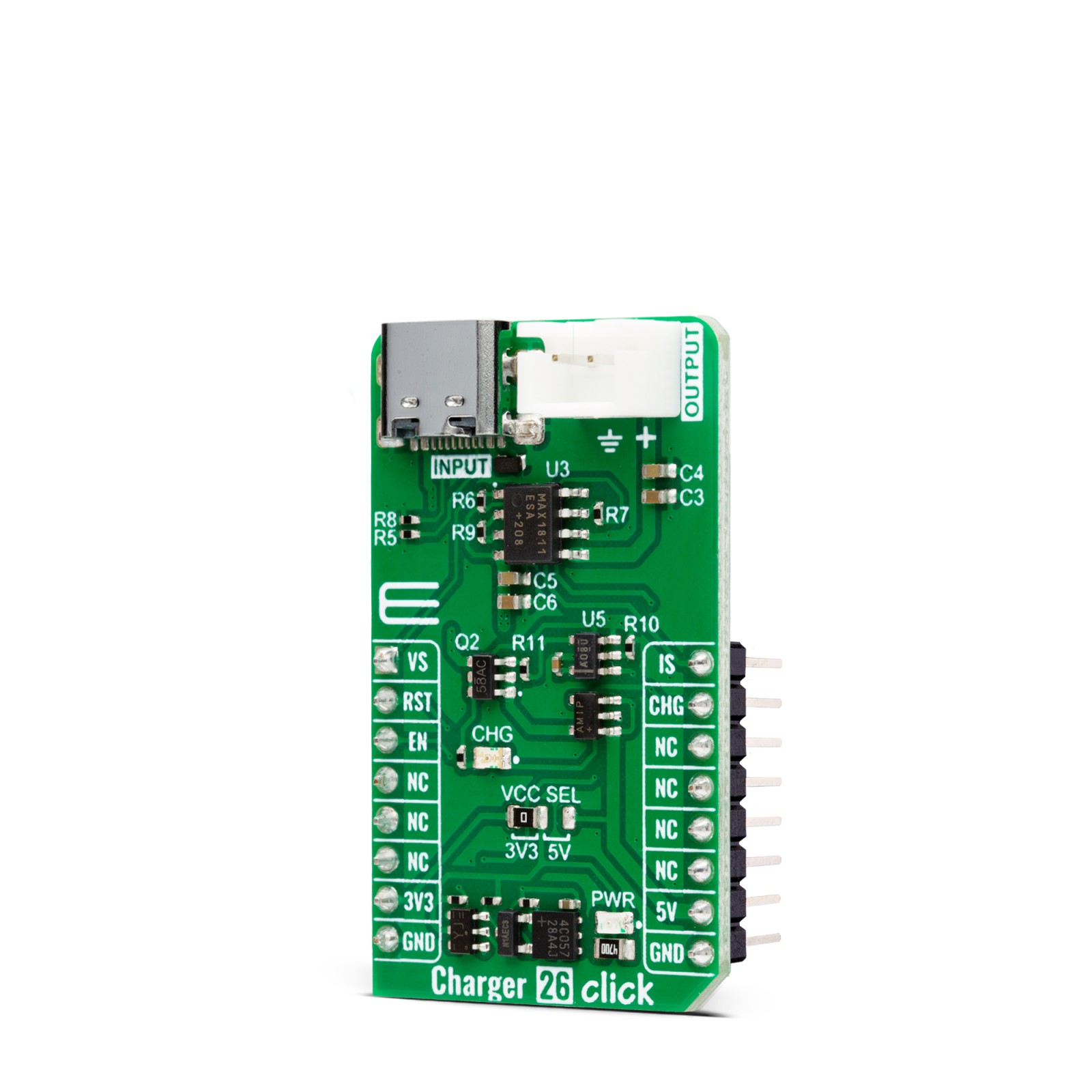
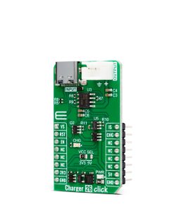
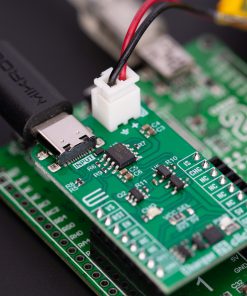
Charger 26 Click is based on the MAX1811, a USB-powered Li+ charger from Analog Devices. The voltage/current regulator of the MAX1811 consists of a voltage control loop, a current control loop, and a thermal control loop. The charger allows you to set the battery regulation voltage to a 4.1V or 4.2 single Li+ cell. It also allows you to set the battery’s charging current in either 100mA or 500mA modes. You should note that by charging the battery over the powered USB host, you can select a 500mA mode. An unpowered USB hub is limited to only 100mA.
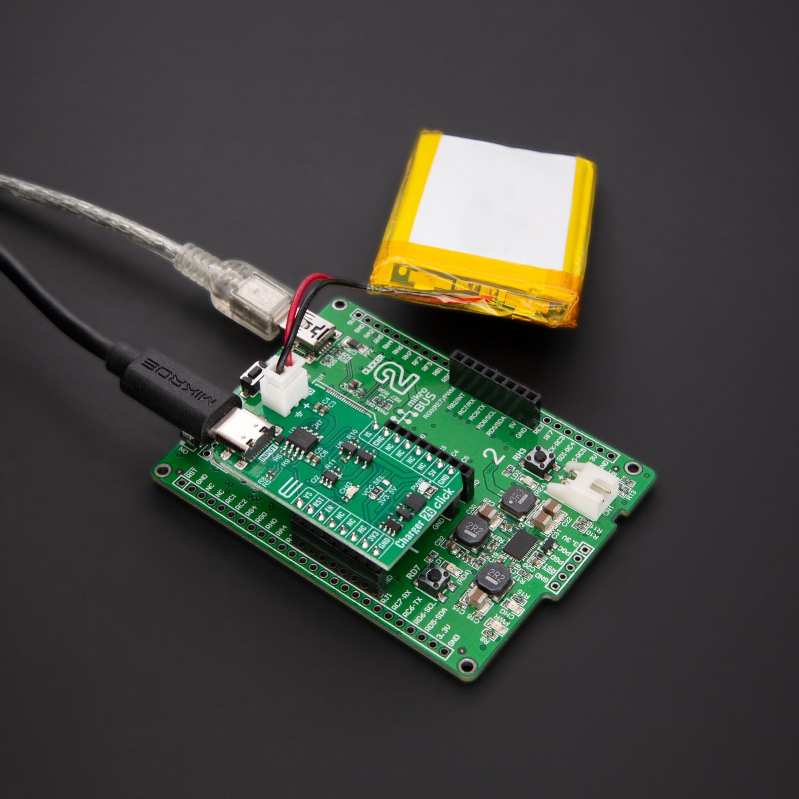
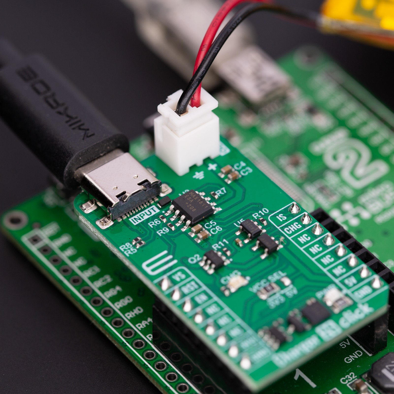
Charger 26 Click is equipped with circuits that will recognize if the MAX1811 is powered over the USB. If not, the MAX1811 will be powered over the 5V mikroBUS™ socket rail. This circuit consists of the MAX40200, an ultra-tiny micropower 1A ideal diode with ultra-low voltage drop from Analog Devices, which will hold the 5V rail if there is a VUSB presence. The SN74AHC1G08, a single 2-input positive-AND gate from Texas Instruments, is here to prevent the MAX1811 charger from being powered from the UCB C input connector if the Charger 26 Click is not connected to a development board equipped with the mikroBUS™ socket. The CHG orange LED is here to indicate the charge status. You can connect the single Li+ cell battery over the JST output connector. Before you do so, please double-check the polarity of the battery.
Charger 26 Click uses the GPIO to communicate with the host MCU. You can select a battery regulation voltage over the VS pin, which, with a pull-up resistor, is set to a 4.2V battery regulation set point. You can also select a battery regulation current over the IS pin, which, with a pull-down resistor, is set to 100mA maximum battery regulation current. Besides the CHG LED, the charging status can be monitored over the CHG output pin. The enable EN pin controls the enable input of the MAX1811 charger, which is enabled by default by the pull-up resistor.
This Click board™ can operate with either 3.3V or 5V logic voltage levels selected via the VCC SEL jumper. This way, both 3.3V and 5V capable MCUs can use the communication lines properly. Also, this Click board™ comes equipped with a library containing easy-to-use functions and an example code that can be used as a reference for further development.
Specifications
Type
Battery charger
Applications
Can be used for the development of PDAs, digital still cameras, MP3 players, cell phones, hand-held devices, and more
On-board modules
MAX1811 – USB-powered Li+ charger from Analog Devices
Key Features
Charges single-cell Li+ batteries directly from the USB C connector, or over the 5V rail of the mikroBUS™ socket, high overall charging accuracy, selectable charging current and voltage, charging indicator, soft start of near-dead battery, checking for fault conditions, and more
Interface
GPIO
Feature
ClickID
Compatibility
mikroBUS™
Click board size
M (42.9 x 25.4 mm)
Input Voltage
3.3V or 5V,External
Pinout diagram
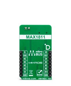
This table shows how the pinout on Charger 26 Click corresponds to the pinout on the mikroBUS™ socket (the latter shown in the two middle columns).
Onboard settings and indicators
Label | Name | Default | Description |
---|---|---|---|
LD1 | PWR | – | Power LED Indicator |
LD2 | CHG | – | Charging LED Indicator |
– | VCC SEL | Left | Logic Level Voltage Selection 3V3/5V: Left position 3V3, Right position 5V |
Charger 26 Click electrical specifications
Description | Min | Typ | Max | Unit |
---|---|---|---|---|
Supply Voltage | 3.3 | – | 5 | V |
Charger Input Supply Voltage | – | 5 | – | V |
Charging Voltage Range | 4.1 | – | 4.2 | V |
Charging Current Range | 100 | – | 500 | mA |
Software Support
We provide a library for the Charger 26 Click as well as a demo application (example), developed using MIKROE compilers. The demo can run on all the main MIKROE development boards.
Package can be downloaded/installed directly from NECTO Studio Package Manager (recommended), downloaded from our LibStock™ or found on Mikroe github account.
Library Description
This library contains API for Charger 26 Click driver.
Key functions
-
charger26_set_vsel
Charger 26 select charger voltage function. -
charger26_set_isel
Charger 26 select charger current function. -
charger26_get_chg_state
Charger 26 chg pin reading function.
Example Description
This example demonstrates the use of Charger 26 Click board™ by enabling the device and then reading and displaying the charger status.
void application_task ( void )
{
if ( CHARGER26_PIN_STATE_LOW == charger26_get_chg_state( &charger26 ) )
{
log_printf( &logger, " Battery is charging. rn" );
}
else
{
log_printf( &logger, " Battery isn't charging, disabling output. rn" );
charger26_enable_output ( &charger26, CHARGER26_DISABLE_OUTPUT );
for ( ; ; );
}
Delay_ms( 1000 );
}
The full application code, and ready to use projects can be installed directly from NECTO Studio Package Manager (recommended), downloaded from our LibStock™ or found on Mikroe github account.
Other Mikroe Libraries used in the example:
- MikroSDK.Board
- MikroSDK.Log
- Click.Charger26
Additional notes and informations
Depending on the development board you are using, you may need USB UART click, USB UART 2 Click or RS232 Click to connect to your PC, for development systems with no UART to USB interface available on the board. UART terminal is available in all MIKROE compilers.
mikroSDK
This Click board™ is supported with mikroSDK – MIKROE Software Development Kit. To ensure proper operation of mikroSDK compliant Click board™ demo applications, mikroSDK should be downloaded from the LibStock and installed for the compiler you are using.
For more information about mikroSDK, visit the official page.