How does it work?
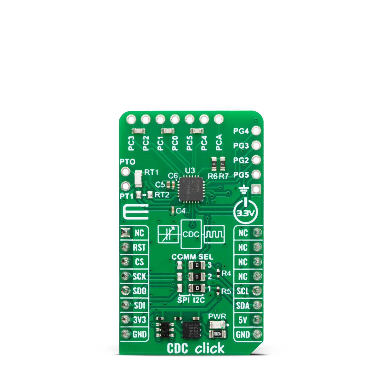
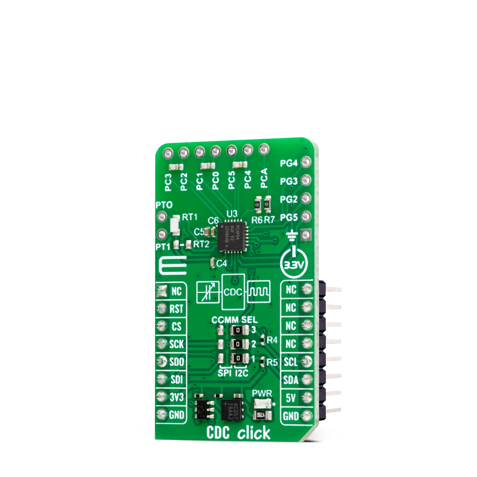
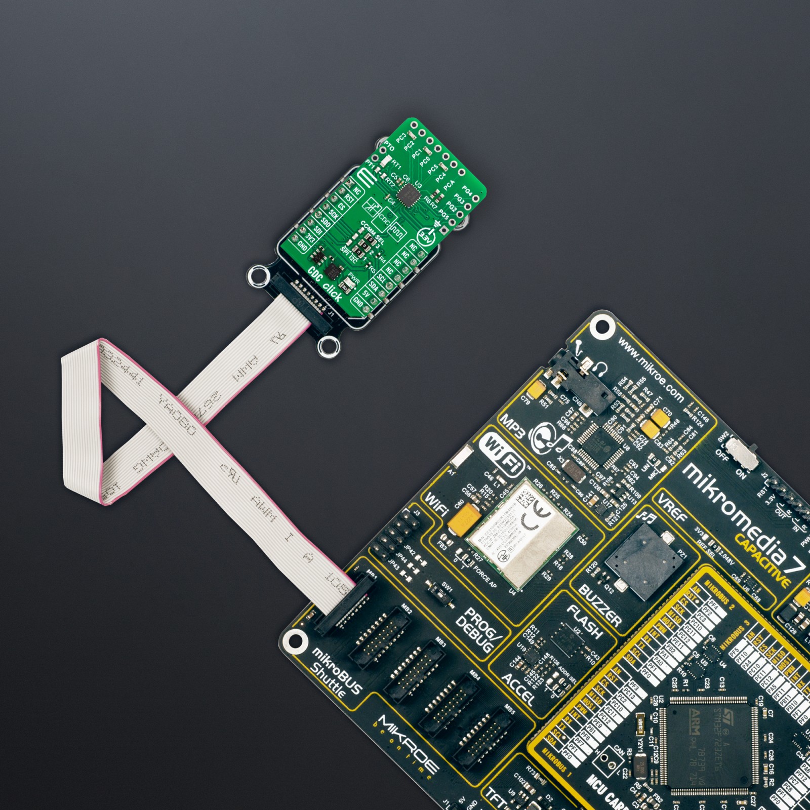
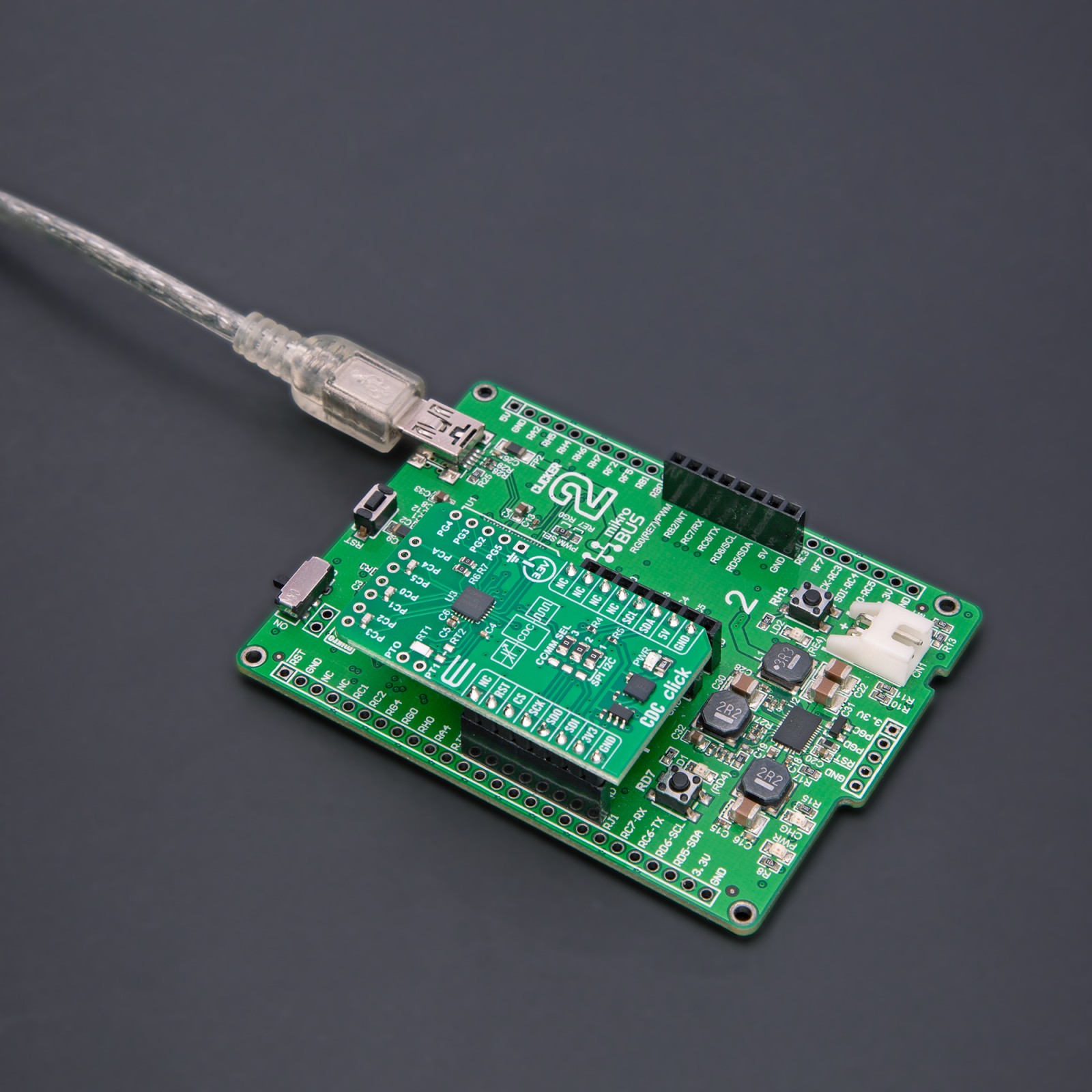
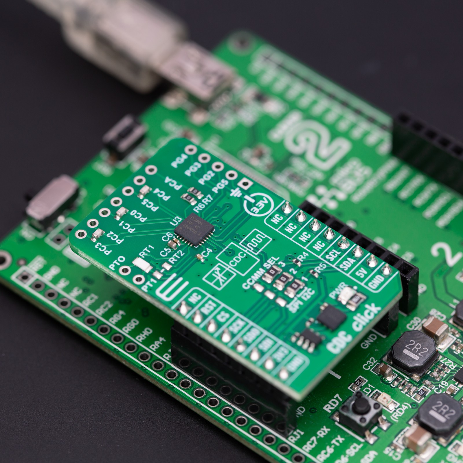
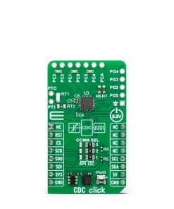
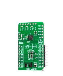
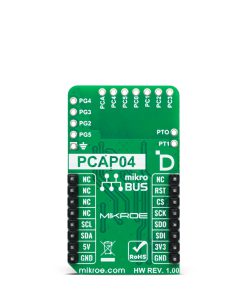
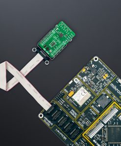
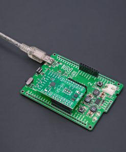
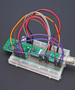
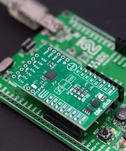
CDC Click is based on the PCAP04, a capacitance-to-digital converter from ScioSense. It covers a wide capacitance input range from a few femtofarads to several hundreds of nanofarads. Configuring the PCAP04 for different capacitance measurement tasks, such as single and differential sensors in grounded or floating connections, is easy. The CDC Click is pre-assembled with 10pF capacitors on the PC0 – PC5 header to emulate capacitive sensors. They are connected as single sensors in floating mode. There is a GND connector for connecting the capacitive sensors in grounded mode. The typical value of the capacitive sensors that can be connected is in the range of 30pF to 3.5nF.
The PCAP04 has four general-purpose input/output pins (PG prefix) and can be used as pulse-density/pulse-width modulation outputs. The PCAP04 features the RDC (resistance-to-digital converter) as well. The RDC unit is mainly intended for measuring temperature, using an internal sensor and reference, or using external resistors like the PT1000 onboard. You can, however, connect an external sensor over the PT1 and PTO connectors or any other resistance element. The DSP takes information from both the CDC and RDC, processes it, and makes it available to the host MCU. You can also add another temperature sensor or temperature reference on RT2. The auxiliary port (PCAUX – PCA on CDC Click) can be used for external compensation capacitance or external discharge resistor and guarding port. You can make a selection by soldering an R7 jumper.
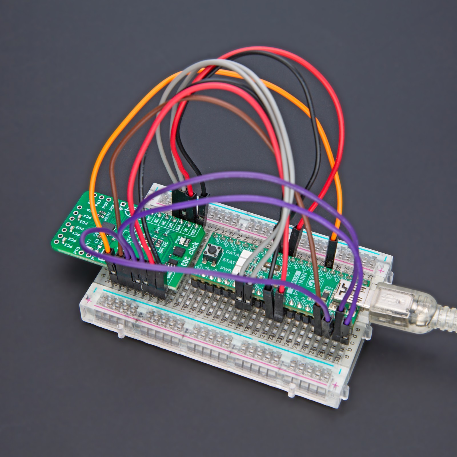
CDC Click can communicate with the host MCU using a standard I2C interface or a 4-wire SPI serial interface. The selection can be made over the COMM SEL jumpers. The I2C is set by default and supports up to 100kHz of the bus frequency clock. The SPI clock frequency is up to 20MHz.
This Click board™ can be operated only with a 3.3V logic voltage level. The board must perform appropriate logic voltage level conversion before using MCUs with different logic levels. Also, it comes equipped with a library containing functions and an example code that can be used as a reference for further development.
Specifications
Type
Capacitive
Applications
Can be used for the development of measuring devices, industrial applications, sensitive equipment, and more
On-board modules
PCAP04 – capacitance-to-digital converter from ScioSense
Key Features
Capacitance-to-digital converter, resistance-to-digital converter, high flexibility, ultra-low power, high resolution, high speed, on-chip DSP for sensor algorithms, on-chip and external temperature measurement capabilities, and more
Interface
I2C,SPI
Feature
ClickID
Compatibility
mikroBUS™
Click board size
M (42.9 x 25.4 mm)
Input Voltage
3.3V
Pinout diagram
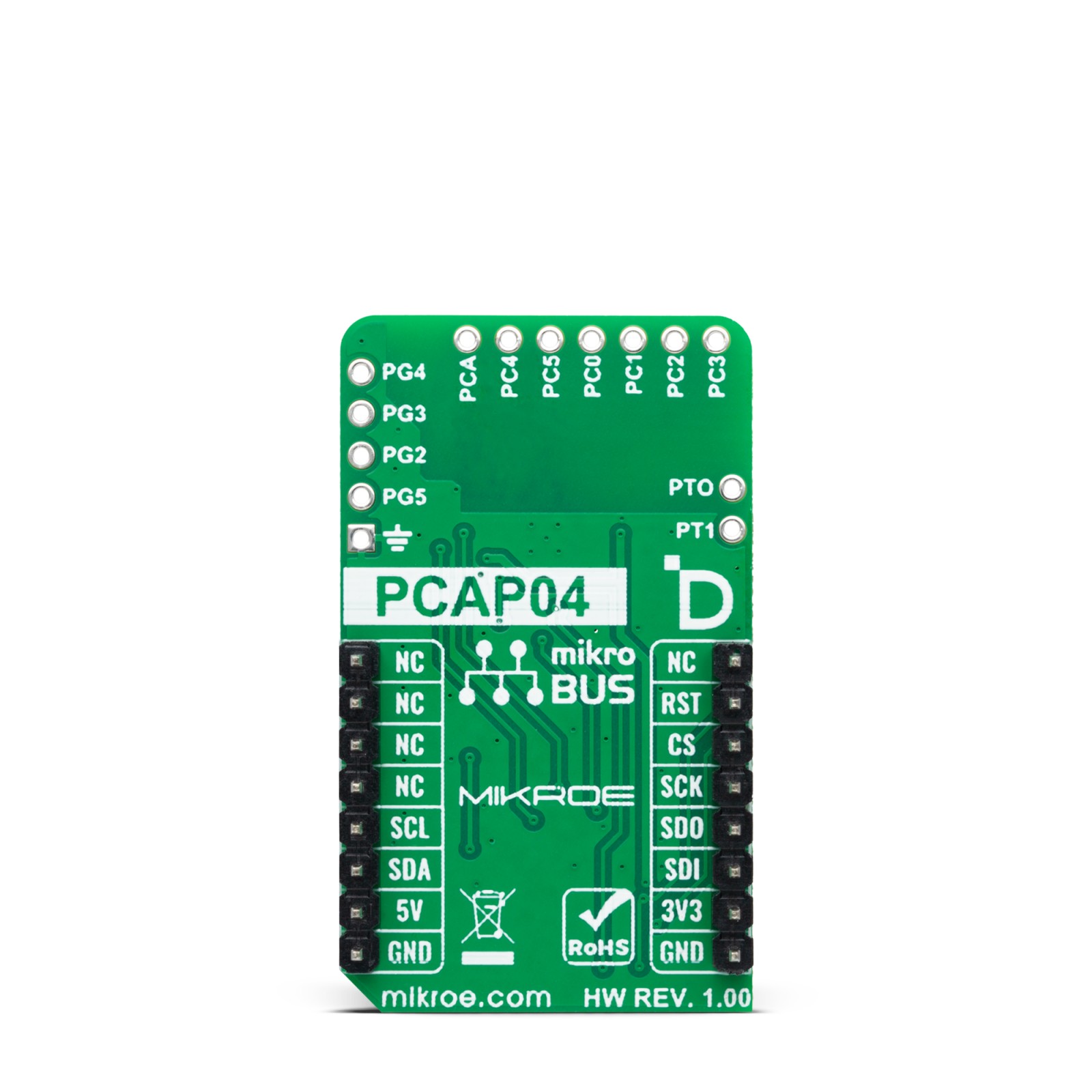
This table shows how the pinout on CDC Click corresponds to the pinout on the mikroBUS™ socket (the latter shown in the two middle columns).
Onboard settings and indicators
Label | Name | Default | Description |
---|---|---|---|
LD1 | PWR | – | Power LED Indicator |
JP1-JP3 | COMM SEL | Right | Communication Interface Selection SPI/I2C: Left position SPI, Right position I2C |
RT2 | RT2 | Unpopulated | External temperature sensor or temperature reference |
R7 | R7 | Populated | Auxiliary port mode selection |
CDC Click electrical specifications
Description | Min | Typ | Max | Unit |
---|---|---|---|---|
Supply Voltage | – | 3.3 | – | V |
Capacitive Sensors Operating Range | 0.03 | – | 3.5 | nF |
Sampling Range | – | – | 50 | kHz |
Resolution | – | – | 20 | bit |
Software Support
We provide a library for the CDC Click as well as a demo application (example), developed using MIKROE compilers. The demo can run on all the main MIKROE development boards.
Package can be downloaded/installed directly from NECTO Studio Package Manager (recommended), downloaded from our LibStock™ or found on Mikroe github account.
Library Description
This library contains API for CDC Click driver.
Key functions
-
cdc_write_config
This function writes configuration data starting from the selected config address. -
cdc_send_opcode
This function sends a desired opcode command byte. -
cdc_read_results
This function reads all results and status registers.
Example Description
This example demonstrates the use of CDC Click board™ by reading capacitance measurements from C3/C2 and C5/C4 ports calculated from pure capacitance ratio between those ports and port C1/C0 which is used as external C reference.
void application_task ( void )
{
cdc_results_t results;
cdc_send_opcode ( &cdc, CDC_OPCODE_CDC_START );
Delay_ms ( 200 );
if ( CDC_OK == cdc_read_results ( &cdc, &results ) )
{
log_printf ( &logger, " C1/C0: %.1f pFrn",
results.res_0 * CDC_REF - CDC_INT_CAP_PF );
log_printf ( &logger, " C3/C2: %.1f pFrn",
results.res_1 * CDC_REF - CDC_INT_CAP_PF );
log_printf ( &logger, " C5/C4: %.1f pFrnn",
results.res_2 * CDC_REF - CDC_INT_CAP_PF );
Delay_ms ( 1000 );
}
}
The full application code, and ready to use projects can be installed directly from NECTO Studio Package Manager (recommended), downloaded from our LibStock™ or found on Mikroe github account.
Other Mikroe Libraries used in the example:
- MikroSDK.Board
- MikroSDK.Log
- Click.CDC
Additional notes and informations
Depending on the development board you are using, you may need USB UART click, USB UART 2 Click or RS232 Click to connect to your PC, for development systems with no UART to USB interface available on the board. UART terminal is available in all MIKROE compilers.
mikroSDK
This Click board™ is supported with mikroSDK – MIKROE Software Development Kit. To ensure proper operation of mikroSDK compliant Click board™ demo applications, mikroSDK should be downloaded from the LibStock and installed for the compiler you are using.
For more information about mikroSDK, visit the official page.