How does it work?
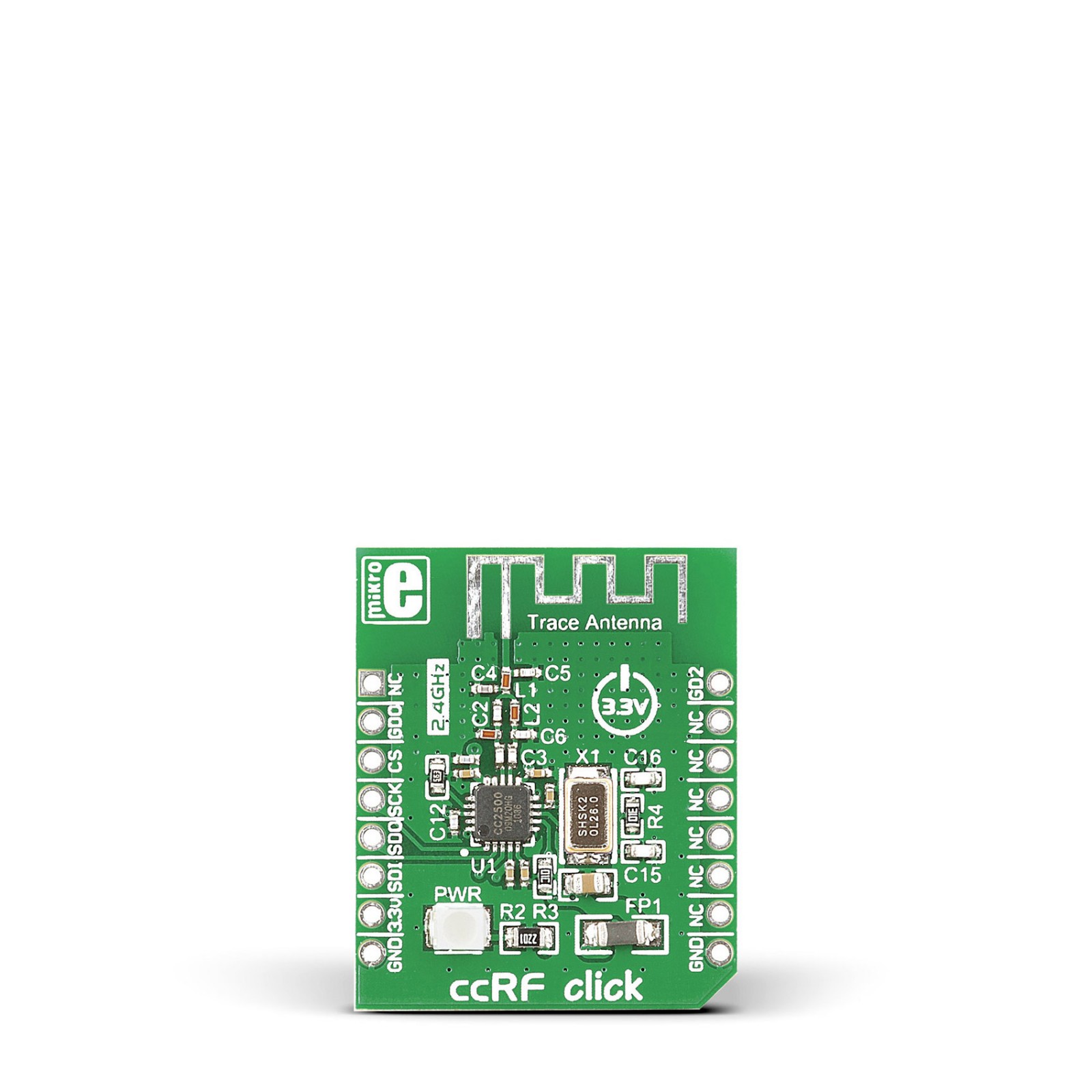
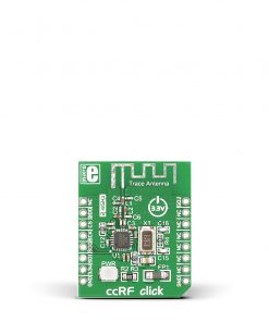
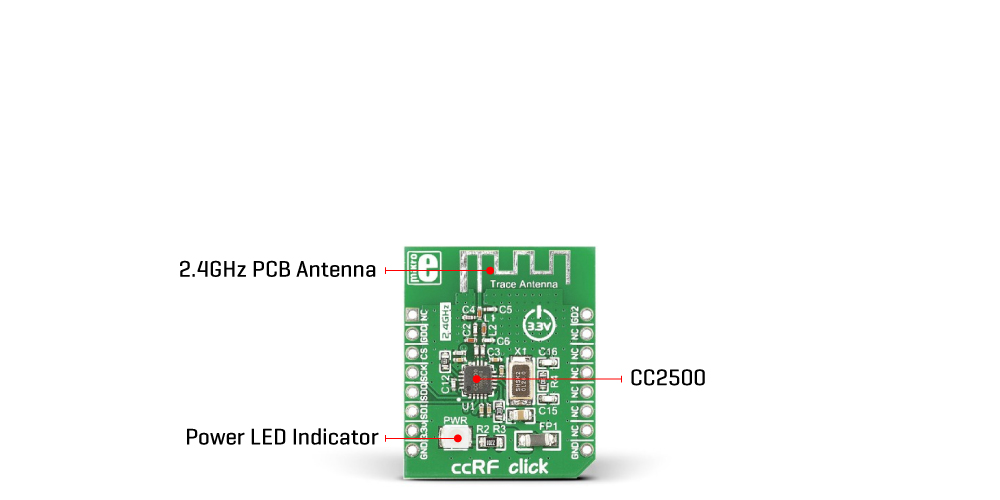
ccRF Click is based on the CC2500, a low-power, high-performance 2.4GHz transceiver from Texas Instruments, operating in the worldwide ISM frequency band from 2400MHz to 2483.5. The CC2500 has excellent receiver selectivity and blocking performance with an embedded packet handler engine suitable for packet-oriented systems. It also has a highly configurable baseband modem that supports various modulation formats (OOK, 2-FSK, GFSK, and MSK) and user-configurable parameters like frequency channel, output power, and air data rate. The transceiver comes with a programmable data rate from 1.2 to 500kBaud depending on frequency range over a PCB trace 2.4GHz antenna, making the ccRF Click suitable for ultra-low power designs.
The CC2500 has a built-in state machine that switches between different operation states (modes) to achieve optimum performance for many applications. Change of the states is performed using command strobes or internal events such as TX FIFO underflow. These states take care of Sleep mode, Idle mode, Active mode, Receive or Transmit mode, Wake-on-Radio (WOR), and more. In addition, the CC2500 comes with on-chip support for synchronization word detection, address check, flexible packet length, and automatic CRC handling.
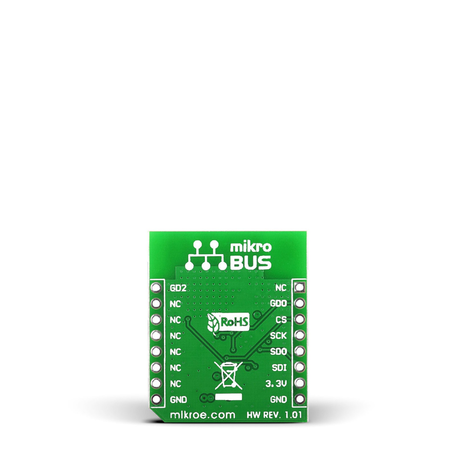
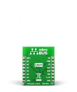
The ccRF Click uses an SPI serial interface to communicate with the host MCU. There are two pins in addition, the GD0 and GD2, routed where the RST and PWM pins of the mikroBUS socket stand by default. With the GD2 as a digital output pin, the user can get test signals, FIFO status, clear channel indicator, serial output RX data, and more. The GD0 as a digital output pin can be used to get the same data as the GD2, plus it can provide serial input TX data.
This Click board™ can be operated only with a 3.3V logic voltage level. The board must perform appropriate logic voltage level conversion before using MCUs with different logic levels. However, the Click board™ comes equipped with a library containing functions and an example code that can be used, as a reference, for further development.
Specifications
Type
2.4 GHz Transceivers,ccRF
Applications
Can be used for home appliances, remote control applications, consumer electronics, and more
On-board modules
CC2500 – 2.4GHz RF transceiver from Texas Instruments
Key Features
High sensitivity, ISM/SRD frequency band, programmable data rate, low power consumption, high performance, supports various modulation formats, flexible support for packet oriented systems, SPI interface, and more
Interface
SPI
Feature
No ClickID
Compatibility
mikroBUS™
Click board size
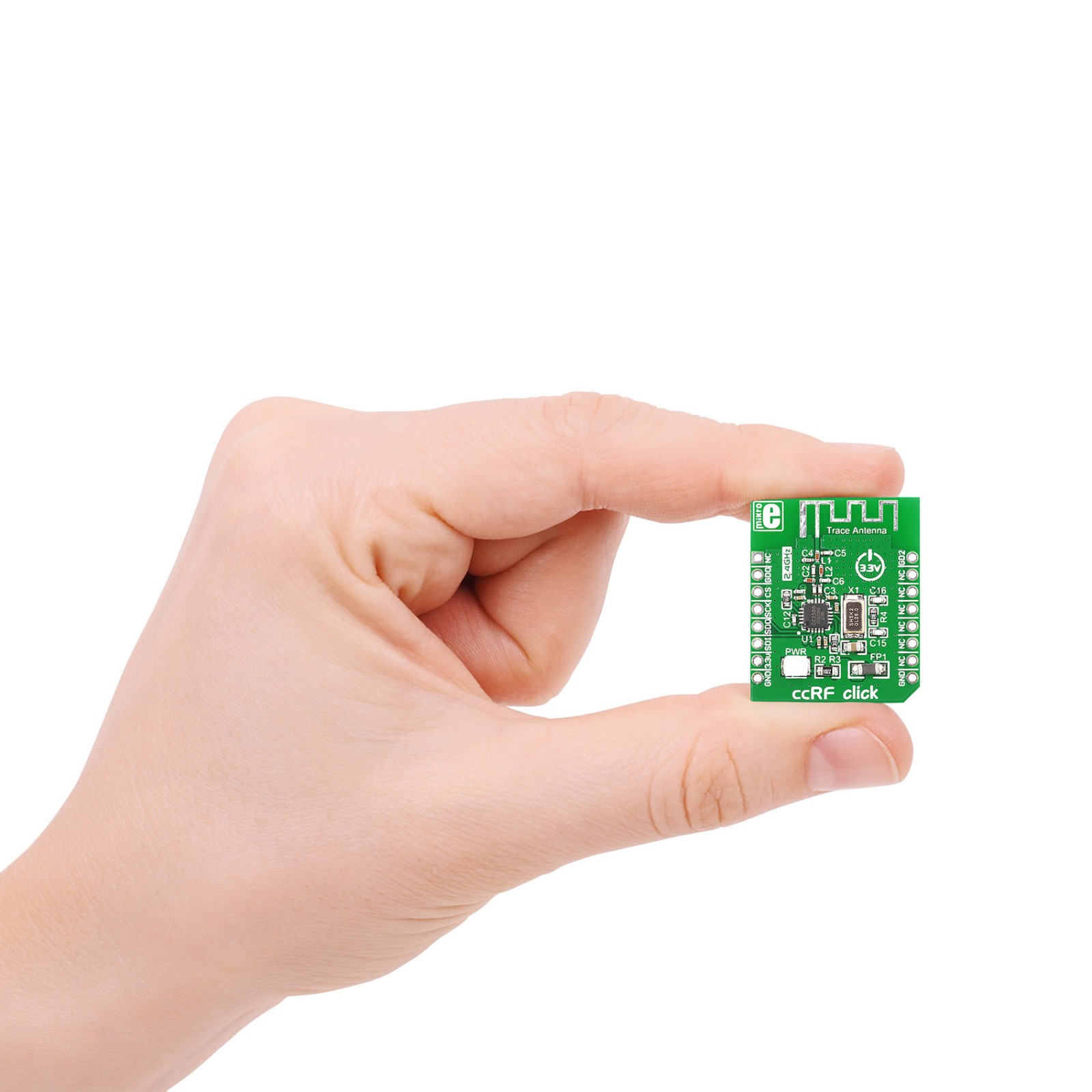
S (28.6 x 25.4 mm)
Input Voltage
3.3V
Pinout diagram
This table shows how the pinout on ccRF Click corresponds to the pinout on the mikroBUS™ socket (the latter shown in the two middle columns).
Onboard settings and indicators
Label | Name | Default | Description |
---|---|---|---|
LD1 | PWR | – | Power LED Indicator |
ccRF Click electrical specifications
Description | Min | Typ | Max | Unit |
---|---|---|---|---|
Supply Voltage | – | 3.3 | – | V |
Frequency range | 2400 | – | 2483.5 | MHz |
Data rate | 1.2 | – | 500 | kBaud |
Receiver sensitivity @ 2.4kBaud | – | -104 | – | dBm |
Software Support
We provide a library for the ccRF Click as well as a demo application (example), developed using MikroElektronika compilers. The demo can run on all the main MikroElektronika development boards.
Package can be downloaded/installed directly from NECTO Studio Package Manager(recommended), downloaded from our LibStock™ or found on Mikroe github account.
Library Description
This library contains API for ccRF Click driver.
Key functions
-
Function transmit a packet with packet length up to 63 bytes to the targeted 8-bit register address
-
Function receive a packet of variable packet length ( first byte in the packet must be the length byte )
-
Function for getting state of GD0 pin function
Example Description
ccRF click communicates with the target microcontroller via mikroBUS SPI, RST and PWM lines. It features Low-Power RF transceiver as well as PCB trace antenna. Maximum device range is up to 20 meters in open space.
void application_task ( void )
{
mode_selected = CCRF_RX_MODE;
switch ( mode_selected )
{
case CCRF_TX_MODE :
{
log_printf( &logger, " TX Mode rn" );
break;
}
case CCRF_RX_MODE :
{
log_printf( &logger, " RX Mode rn" );
break;
}
case CCRF_IDLE_MODE :
{
log_printf( &logger, " Idle Mode rn" );
break;
}
}
switch( mode_selected )
{
case CCRF_TX_MODE :
{
length_tx = sizeof( tx_buffer );
ccrf_transmit_packet( &ccrf, &tx_buffer[ 0 ], length_tx );
Delay_ms( 1000 );
break;
}
case CCRF_RX_MODE :
{
length_rx = sizeof( rx_buffer );
if ( ccrf_receive_packet( &ccrf, &rx_buffer[ 0 ], &length_rx ) )
{
for ( cnt = 0; cnt < length_rx; cnt++ )
{
log_printf( &logger, " rx_buffer[ %d ] = %c rn", cnt, rx_buffer[ cnt ] );
}
log_printf( &logger, "----------------------rn" );
Delay_ms( 1000 );
}
break;
}
}
}
The full application code, and ready to use projects can be installed directly from NECTO Studio Package Manager(recommended), downloaded from our LibStock™ or found on Mikroe github account.
Other Mikroe Libraries used in the example:
- MikroSDK.Board
- MikroSDK.Log
- Click.ccRf
Additional notes and informations
Depending on the development board you are using, you may need USB UART click, USB UART 2 Click or RS232 Click to connect to your PC, for development systems with no UART to USB interface available on the board. UART terminal is available in all MikroElektronika compilers.
mikroSDK
This Click board™ is supported with mikroSDK – MikroElektronika Software Development Kit. To ensure proper operation of mikroSDK compliant Click board™ demo applications, mikroSDK should be downloaded from the LibStock and installed for the compiler you are using.
For more information about mikroSDK, visit the official page.